


Arduino CPUs and Motor Shields
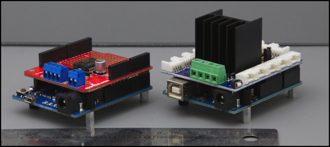
Arduino Uno and Ardumoto (left) and Arduino Leonardo and seeed studios V1 motor shield (right)
I’m still playing with Arduinos this week, but the little beasties are multiplying. That’s partly because I want to be able to test with the various CPU architectures, but also because each has unique strengths and weaknesses, and I’m still evaluating which of them is going to be the right choice for my tram controller. At the same time, it turns out that there are a number of options for motor shields, as I mentioned last time, and they too have strengths and weaknesses.
I’ve put a lot of the info I’ve collected on a page describing Arduinos and Shields. I’ve also updated my Testing page with some thoughts about filtering the PWM output (I’ll say a bit on that below). And I’ve been working on the plan for the sensors, although not much has been done there yet. Mostly today’s post summarizes what I plan to use for the final layout, and what I’m presently using for testing purposes.
And never fear, I’m continuing to work on the software, although I spent much of this week rewriting the stuff I’d done so far into a more polished form, adding some features, and converting it to an Arduino library. It’s mostly working now, but I decided to make some improvements, such as adding momentum, and I’m still working on that.
Combinations and Trade-offs
There is a lot of choice in the selection of Arduinos, and several different motor shields, all slightly different. So, which to use? Right now I’m leaning to use of the Arduino Leonardo with the seeed studio V2 motor shield and V2 relay shield. I chose the V2 motor shield because while it has a heat sink, it’s a low-profile one that doesn’t prevent stacking the relay shield with it. But for the moment, I have to compromise and use what I have for current testing.
What I like about the Leonardo in particular is the absence of the bulky standard USB connector. It also has the reset button in an easily-accessible location (as does the new Uno). The downside of the Leonardo is that it can’t really be used with the Arduino Motor Shield or the Ardumoto, as both use pins that depend on Timer0 in the Leonardo. I’ll get to that below.
PWM, Timers and Pins
Yes, more about PWM. To recap: in order to run a DC motor, you need variable voltage. With digital circuits, the way to get variable voltage is to use PWM. And as anyone who’s worked with DCC decoders (which also use PWM) will recall, PWM has a frequency, and “supersonic” is a good thing to have. It’s good because lower-frequency PWM will cause the motor or drive mechanism to vibrate at audible frequencies. And low frequency PWM will cause coreless motors to overheat (it’s widely believed, although I haven’t found an authoritative source, the Kato’s Unitram uses coreless motors). So I want ultrasonic PWM out of my Arduino.
Arduino’s by default generate PWM at 489 Hz. But it’s possible to modify this to a supersonic frequency (31 kHz) by changing the configuration of the timer in the Arduino, as I wrote about last time. Each pin on an Arduino that is capable of PWM has an associated Output Compare Register (OCR), and each OCR is linked to a timer. A timer can support more than one OCR, up to six although typically fewer.
How it works is that the throttle setting (desired PWM duty cycle, from 0-255 for 8-bit PWM) is stored in the OCR, and the timer counts up to 255. As long as the timer is below the OCR value, the PWM output is high, once it’s above the OCR value, the output is low. When the timer gets to 255, it restarts from zero, starting a new cycle for the PWM output. (that’s for Fast PWM; Phase-correct PWM is a little different, but it’s basically the same idea). You need both the OCR and the timer working together to generate a PWM signal.
The problem is that some pins use Timer0, and that timer is used for internal things like counting milliseconds (important when working with things like speed and acceleration; I’m using them for the momentum feature I’m adding to my software). Using a pin associated with timer0 means you can’t use supersonic PWM without breaking the standard timing functions, which I’d rather not do (I could create my own using another timer, but I’d rather not).
And which pin goes with which timer depends on the CPU chip used. Different models of Arduino use different CPUs.
The Arduino motor shield design available from Radio Shack (and hence also the Ardumoto which is a simplified variation of that design) uses timer0 for both motors on the Leonardo (and any 32u4 family Arduinos).
Note: Radio Shack is selling the latest Arduino R3 motor shield in my local stores as part 276-131, but it’s no listed in their online catalog.
The DFRobot.com shield uses timer0 for both motors on the Uno (and any 168/328 family Arduinos).
The seeed shields work with all three families of processors as their pins don’t use timer0 on any of those CPUs. Yet another reason to like these (the seeed V1 shield is also available from Radio Shack, part 276-242).
If you want to play with this, the Uno and seeed V1, both available from RS, are a good place to start, but you won’t be able to use the seeed relay shield V1 (sold by RS) with that pairing, you’d need to order the V2 model (and seeed’s in Shenzen, China, so shipping isn’t cheap).
Note: I found the seeed V1 relay shield in my local RS, but if it had a part number, I couldn’t find it.
Testing and Further Development
With the shields I have right now, I have a couple of options for combinations I can work with. I’m still waiting on V2 versions of the seeed motor and relay shields (they’re on the way from China), which means I have to use the V1 relay shield, which must be on the top of a stack, so it can’t be used with the seeed V1 motor shield.
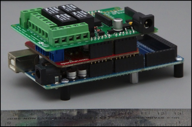
Mega 2560, Ardumoto Motor Shield, and seeed Relay Shield V1
This leaves me with two choices:
1) Relay above Ardumoto, will work on Mega or Uno. The two shields will share power, but be isolated from the Arduino if Vin is cut (as it is on mine).
2) Relay above Arduino Motor Shield, will work only on Uno (due to new pins). Either the relay, motor shield and Arduino will share power, or I can cut the trace on the Arduino Motor Shield and power it separately (which is a good idea), but that still has the relay shield sharing power with the Arduino (I can however use a 12V regulated supply). I’m not thrilled with this, as the relays may inject noise into the Arduino circuitry when they switch (they pull about 60 mA ea, which is a substantial draw).
And with #2, another problem cropped up: the TinkerKit terminals were tall enough, and the relay shield set low enough, that leads protruding from the bottom of the relay shield hit one of the terminals, preventing the board for seating properly.
So out of all the hardware I have so far, only two combinations really work. I’d wanted to use the Leonardo, but I think for now my combination has to be the Mega or Uno with the Ardumoto and the V1 relay. With pin Vin on the Ardumoto cut, the relay shield and motor shield will share a power supply and be isolated from the Arduino itself. This isn’t ideal for the long-term solution, as the power demands of two trains plus all four operating relays could easily exceed 600 mA. But I have some larger 1.2A 12V regulated power supplies, so I can use one of them.
Output Filtering
It’s been a busy week, and I’ve also been thinking about the electrical aspect of driving the train using PWM, and the implications of that. Now we all know you can do it. DCC decoders use PWM. But they also implement sophisticated systems that address limitations of PWM at low duty cycles, adding extra pulses or making them a bit longer, to compensate for the difficulties inherent in a voltage that’s mostly off at those speed. The Arduino can’t do that (well, not from hardware, maybe I could write my own interrupt routines to do so, but life’s too short for that).
The output of a PWM motor controller is a square wave. Square waves and inductors (like the coils in the motor) don’t really get along all that well. The use of supersonic PWM helps to an extent, but at low duty cycles (low average voltages) there’s still a considerable mismatch. So I’d wondered if there was anything I could do to smooth out that waveform, thinking vaguely about a using a capacitor somehow. My hope was that this would allow the train to move at lower duty cycles, providing a smoother overall response. It would need to not store power too long, since I want the motor to stop or change speed responsively when the throttle is adjusted. If it could average out the square wave somewhat, that would be an advantage. Googling about, I found contradictory advice from “it won’t work” to “it’s terribly inefficient” to “you must do it” (which, of course, I know is untrue).
But among the noise, I found someone who’d done just that with an Arduino, using what is essentially a low-pass filter, and they even had a link to a calculator for working out suitable sizes (although I found it more useful to check the results of my own work than to discover the values I needed). After deciding I needed a resistor around 5 ohms and a 100 microfarad (100 MFD) capacitor, I discovered just how much the latter would cost (over US$50 each). At that point I scaled back slightly to a 47 MFD capacity, which isn’t significantly worse but costs half as much (I also looked at smaller ones, but the ripple increases significantly).
And then I simulated them using the modeling tool Don had pointed out a couple of months ago, at falstad.com:
Note: for some reason I can’t save the URL to my assembled model (looks like a software issue with the version of Java on my computer), so these two screen grabs will have to do.
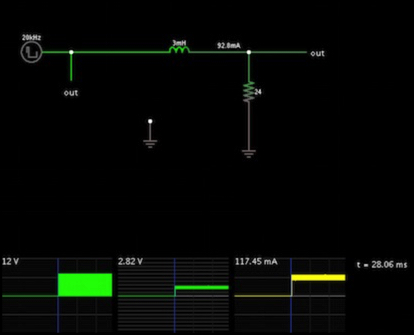
Kato Loco on unfiltered PWM (20 kHz, 20% duty cycle)
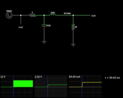
Kato Loco on filtered PWM (20 kHz, 47 MFD filter capacitor & 5 ohm resistor, 20% duty cycle)
What’s of interest is the thickness of the horizontal line in the center and right graphs: this shows the amount of “ripple” in the output. The other thing is that even without the filter, I’m still getting a horizontal line, due to the inductive effect of the motor. So what this filter is buying me is more even output voltage (and perhaps some life-extension of the motor), but not a substantial change to the voltage provided over time. This suggests that I probably won’t see much variation in the behavior of the locomotive. I’m still planning to try, although perhaps not immediately.
Update 4/29/13: Don pointed out that I could build a filter that connected the capacitor to ground (which is essentially what I modeled above) and use polarized electrolytic capacitors, which are available in 100 MFD size for a couple of bucks. For some reason I’d only been thinking about the filter going between the motor outputs, which would require an unpolarized filter capacitor. I expect to do this, but it’s on my list of things to do at present.
And that’s it for this week. I think it’s enough.