


Tram Controller Status
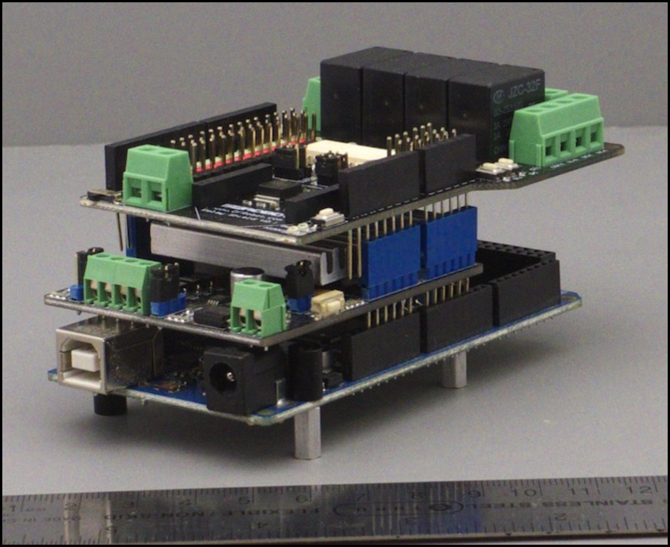
DFRobot Relay shield (V2.1) above Mega 2560 R3 with the dead seeed V2 motor shield in the middle
I’m continuing to work on the Tram Controller project (main page, past musings), to the exclusion of all else layout-related, which doesn’t make for interesting posts here. But I’ve made a number of decisions in the past month, and it’s probably worth summarizing them and where that puts the project overall. Short answer: making good progress, but slower than anticipated (what else is new; all my projects run “slower than anticipated”).
I’ve also been thinking about the diorama-like layout I’m going to initially use this with. The current candidate plans for that are on the new One Point Five Meter Line page.
But now for the Arduino stuff:
Software
First, as noted before, I’ve been taking the various things I developed separately, like sensor management and keybounce processing, and putting them into a new “Tram Controller” Arduino sketch. This has actually been more work than anticipated, because some of that earlier code was quite messy (when things don’t work, I tend to hack at them until they do, and then go back later and clean them up; in some cases “later” never came).
The worst example of this was my IR photo-detector occupancy sensors. The code for that worked. It was also several hundred lines of horrible spaghetti with a number of unnecessary relics left in it. When I went to copy it into the new program, I couldn’t even figure out what it was doing at first. As any beginning programming class will teach you, that’s not a good way to program. Well, it’s not like I have a degree on Computer Science. Oh, wait, I do have a degree in Computer Science, don’t I? I never was a very good student...
So, what I did, or rather, am doing, for the sensor code is to rewrite it as a class in a library, with all of the complexity hidden from the caller. After setup, you just have to call a “readSensors” method, and you’ll get back an array of booleans indicating which changed this time (there’s a second method to call to see the last-read state of a sensor, so you can get that as needed). As long as readSensors gets called every millisecond or two, it’s going to catch changes promptly enough for running trains, and that most-recent-state array will reflect reality. The library is working, but not yet ready for release. Once it’s working, I’ll put it up on GitHub alongside the TrainMotor library. And then I can go back to working on the program that needs to call it.
One thing I discovered was that the original code had some problems if room lighting changed, as I’d never gotten around to implementing the “keep track of ambient light level and don’t let it bias sensors” code. That’s a big part of what I’m working on now. I’ve also trimmed down the amount of information per sensor that needs to be kept (it was saving a bunch of things it could compute on the fly).
Track
I haven’t changed what I’m using for track, but I have bought what I need to build a test track on my workbench (dinning room table) so I can put some breadboarded detectors and signal-equivalent LEDs along the track and start testing the actual control program. As part of this I’ve run across a problem with the Tomix switches I’m using that I hadn’t had to deal with when using them on a DC power pack.
Although these are slip switches, and hence both routes through the switch should be live at all times, the switches are wired in such a way that the non-selected route has a dead zone if you insulate the switch from the external track. That’s not good with trams, which tend to have short wheelbases and may not have all-wheel pickup.
My switches will be permanently set for the through route (lower diagram below), so that a tram leaving the station left of the switch goes straight (left-hand running). Trains entering via the diverging route push the spring-loaded point rails out of the way (which doesn’t change the setting of the switch or the electrical connections).
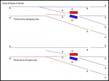
Now I knew this (I drew that diagram two years ago for my Tomix Track page), but I’d forgotten it. And I don’t think I’d ever considered what it meant for my planned use. I’d been assuming I had to insulate the four rails on the right side of the diagram. And that gives me a dead zone (shown in black and marked “x” above).
The problem is that if I don’t insulate the through route on the right side, when the left side is switched to the diverging route power, I’ll be shorting the diverging route “Red” to the through route “Red”, which by definition will be at opposite polarities when a tram is entering the station (since the upper line is always polarized for motion away from the station). For a general solution, allowing the switch to be thrown to either route, I’d need to insulate all four rails (hence my original plan).
However, since I never actually throw the switch, it should be the case that I can insulate the two rails of the through route (red and blue), and the rails between there and the frog will get their power from the station-side rails, while I leave the diverging route tracks (black) uninsulated, so the portions marked in black in the lower diagram above get their power from the diverging route rails. This avoids any dead zones, and as long as the switch is never thrown to the diverging route it also should avoid any short circuits.
I have to finish assembling the test track on the workbench and try this out to be certain it’s safe, but testing with a multimeter appears to show it as okay, and visual inspection doesn’t show any places where a short against the wheels looks likely.
Arduinos and Shields
As I mentioned last time, adding trackside signals is going to cause me to switch to use of the Mega 2560 model of Arduino, rather than the Uno, adding to the overall cost (not counting the cost of those signals). I’ve also decided to change both the motor controller and the way I’m going to do relays for controlling the track blocks.
One problem is my Mega: it’s the original (non-R3) version from two years ago. It has a couple of metal capacitors when the new pins of the R3-series boards go, which means an R3-compatible shield (and a number of mine are), has pins that would touch those, causing a short circuit.
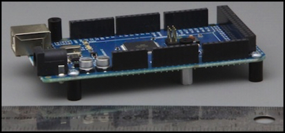
Original Mega, with the two silver capacitors in the wrong place
So, I needed to get a new R3 version of the Mega. I can keep the old one for software development on the workbench, so it’s not a total loss. While these continue to list at US$60, my local Micro Center had several (in Arduino boxes and marked “Made in Italy”) for US$35, not much more than an Uno. That’s it up top, and you can see by comparison with the photo here that the capacitors have been relocated away from where the pins would be, and it has the additional headers for the new pins anyway.
The next issue is the motor controller. After I burned out my seeed studios motor shield (apparently by using an external power supply) I’d initially planned to go back to the Ardumoto. That would work, but it requires cutting the +5V pin, meaning another shield can’t be stacked above it (although it could be the top of the stack. I also don’t like the lack of a heat sink for something that will be driving two motors continuously without much of a break. I expect it would work, particularly if I glue a small heat sink (like this one) to the chip.
But while I was dithering, I ran across a motor shield that promised to be more suitable for the continuous-duty use I envisioned: the Rugged Circuits Rugged Motor Driver Shield (yes, they use the word “rugged” a lot; subtle they aren’t). This uses the usual Aduino Motor Shield / Ardumoto pins, so anything that works with those will work with it.
And it’s designed for up to 15V external motor power without cutting any pins (more if you want to cut a trace on it). They even sell an upgrade kit that includes heat sinks, if you want that extra measure of safety margin (although it’s apparently back-ordered).
Related to that was the question of what to do about relays. I’d thought about wiring up my own, but it’s not simply a matter of driving them off the Arduino pins, as the current draw exceeds the pin rating (the most efficient uses 40 mA, just at the limit, and some use 71 mA or even 90 mA per relay). So I went back to thinking about relay shields.
The seed V1 relay shield needs to be the top of the stack, which wouldn’t be a problem as it has its own power jack and needs Vin isolated also. But I was concerned about that external power: they deleted it from the V2 shield and removed all text from their wiki about the V1 shield, and that, coupled with my seeed motor shield’s failure, didn’t leave me feeling good about it.
Their V2 shield was also problematic. Although it’s nicely designed, with a plastic shield on the bottom to prevent other devices from inadvertent contact with pins on the circuit board, and it has good screw terminals, it’s missing one crucial element: the external power jack. It must piggy-back off the Arduino’s supply. And it’s using the inefficient relays, meaning with all four thrown it’s going to pull 284 mA of power (about half the capacity of a typical supply I’d use), and it uses a 5V relay, which means it will be converting my 12V supply to 5V on the Arduino, stressing the voltage regulator chip there, although, to be fair, probably within spec.
The regulator should be able to handle 284 mA in addition to perhaps 100 mA from the Arduino’s chip, as it’s rated to 800 mA, although I don’t know if there are other board limits (this does presuppose I can drive the motor shield from an external source, as it could easily be drawing 300 mA or more when running two trains. While all of that could, in theory, be powered via the Arduino’s regulator, it’s never a good idea to cut that close to the limits of electronic components.
All this had me thinking about the DFRobot Relay shield (their V2 model). It wouldn’t have worked with the Seeed motor shield (pin conflict, which I could have worked around assuming DFRobot’s pin-remapping worked), but it doesn’t have any pin conflict with the Ardumoto (or any of the ones using the same pins, like Rugged Circuits).
The documentation implied it used the more power efficient relays, and it has external screw terminals for a 9V power supply for them. The latter is likely to be required, as mine arrived equipped with different, and very inefficient, relays (90 mA each, so 360 mA when all four are active). One problem is that mounted directly above the Mega, it’s long enough to block use of pins 22 to 53 across the end of the board, so I’ll need to mount it atop the motor shield to ensure room to wire my signals to those pins. And that makes me wonder about mounting it above an Ardumoto. It appears from their wiki that it only takes relay power from the input, and still needs the 5V supply from the Arduino to operate.
So that’s the new plan: Mega 2560 R3, Rugged Motor Shield above that, and DFRobot Relay shield above that. Three power supplies (9V to the Arduino, 9V to the Relay Shield relays, and 12V to the motor shield motors). Plus a separate 12V supply for the IR LEDs driving the sensors (I’ll likely use the same one for that as I use for building lighting). I ordered the necessary parts, and the DFRobot shield has arrived (two days from Shenzen China!), but the Rugged Circuits gear is at the tender mercy of the USPS, which appears to be taking its sweet time about delivering it (nice that I can get stuff from China faster than from halfway across the U.S.).