


MRC Tech 7 780
DC “Power Packs” for model trains tend to be designed for HO scale trains, at least in North America. There are separate ones for G scale, and some multi-scale packs catering to both HO and larger scales. But those sold for N scale are typically just HO models, with the usual HO “16 volt” or higher output, usually called “Universal” power packs.
Maybe it doesn’t really matter, but I’d prefer not to risk my expensive models with a pack that could overload their wiring. Smaller motors are likely to have less tolerance for high currents, and high voltage leads to high currents under load. The NMRA standards are regrettably vague in this area. This important one is S-9 Electrical, which merely notes that the operator is responsible “not to operate in such a manner to exceed the rated current or otherwise overheat the motor.” That might be helpful advice if anyone listed “rated current” and put ammeters on their power packs, but I’ve never seen such a specification for any model, and ammeters are not common. Further, modern power packs may adjust the current with no operator intervention.
The maximum current a motor will draw, its “stall current”, is defined by the design of the motor and the voltage at which it’s operated. So implicitly, there’s a maximum voltage at which to operate such a motor, beyond which the stall current will exceed the rating for the motor, and overheating will result. Maximum voltage is often given on motors: I have an Atlas B23 that lists “Maximum voltage: 12 V DC” on its instruction sheet, and a Kato SD80 that has the same printed on the box. It’s not universal: my Walthers Life-Like GP38 does not mention voltage, maximum or otherwise on its instructions or box. Unfortunately, most of these are routinely operated on systems putting out more voltage. It’s not clear either if these ratings reflect real maximums, of if they’re simply “marketing”, since “everyone knows” N scale uses 12 volts. I suspect the real ratings are higher, and the “12V” is just marketing.
The NMRA, as I’ve mentioned before, fails to actually define a maximum voltage in S-9, even though several other standards point to it for one. It was revised in 1984, and presumably the number was deleted at that time, which seems like a rather serious mistake to me. They do provide some guidance: in S-9.1 DCC Electrical Standard (PDF), there is an appendix defining DCC voltages, which has “typical” numbers for various scales. From the motor numbers, we can deduce that a “typical” N-scale pack is expected to provide 12 volts, and a typical HO-scale pack is expected to provide 14.5 volts. Unfortunately the maximums in that table can’t be used the same way, because they’re defining what DCC environments a decoder might have to survive, which doesn’t imply the limit (which is 24 volts) is something you’d intentionally want to use for a model.
So you see that models that do define a “maximum” actually use the NMRA’s “typical”, and in any case most DC power packs output a whole lot more. Now the conventional response to this is “don’t turn the knob all the way up”. If you don’t have kids, that would work, unless you get distracted, or have a guest operator over, doing something like hauling a too-long train up a long grade. Or if you have a power pack with Back EMF-based compensation, which turns the voltage up to maintain constant speed without human intervention. The MRC Tech II 220 I bought a few years ago will output about 19 volts, and includes some form of Back EMF compensation (MRC calls it “Accutec”), although after examining my new Tech 7, I’m somewhat dubious about their claim.
My take on this: for N scale, get a pack that comes as close to 12V as you can. It probably won’t hurt to use a 15V or even 16V DC power pack, although I’d steer clear of the higher-voltage ones for sure. But there’s no real way to know what the definition of “too much” really is.
Like many other N-scale modelers I’ve used Kato’s power packs. I have three from my first N-scale layout. Although those are marketed for “HO/N” use, they’re referred to as “12 V” packs. As mentioned in my review of that last month, my supplied “15V” external transformer was producing 17 volts, and the 100% output of the pack was rather high. Looking at the scope images (in the DC Testing Album) the scope estimated 100% throttle at 15.8V RMS (but that’s only approximate since the output is neither pure DC nor an AC wave). Now the Kato pack doesn’t do Back EMF, so I could just turn it down (the “red line” on the pack produced about 13.7 V RMS). Or I could buy a separate 14V wall-wart supply, which ought to get me about 12 V RMS, except that those are hard to find unless you want to spend a lot for a multi-voltage supply.
But I decided to see if I could do better, and after looking around I discovered MRC’s new “Tech 7” line of power packs had one model that was rated for 14.5 volts maximum and only 10VA (about 700 mA current at max) per “cab” (throttle knob), and it had two cabs. One of these could replace both Kato packs used on the dual-track “Express Line” on my layout when I had it on DC, which is what I mostly use with it. After checking my local hobby store (which was out of stock and didn’t think they could get it quickly as apparently it’s in high demand) I ordered one from an online store, for about US$75 with shipping. That’s cheaper than a pair of Kato packs, which run about US$50 each, although you can sometimes find them cheaper.
Now I could also have bought a Japanese power pack that really does put out 12 Volts of DC (I run Japanese trains, after all), but those are designed for use on Japan’s 100V electrical system, and not UL-listed, which would be a problem should I ever have a fire that in any way involved them. I have a couple for my tram layout (described on my power pack testing page and my Urban Tram Layout page), but I run them on a 100V step-down transformer and I’m careful to unplug them any time I’m not at the layout. I’d rather not do that with the main layout (it has an off switch, but I don’t unplug it).
The remainder of this post is a review of the MRC Tech 7 power pack, but I’m comparing it to my Kato on the aspects that matter to me. See my earlier review of the Kato pack for more on that one. One of the attractions of the MRC pack is that it’s designed to improve slow-speed running characteristics. The Kato does some of that, but it’s not quite the same thing. So let’s see how it compares.
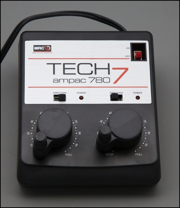
MRC Tech 7 ampac 780
Anyone who’s been involved in model railroading for any length of time knows the Model Rectifier Corporation, more commonly just MRC. They’re probably the dominant supplier of DC power packs for HO and N-scale model railroading in North America, aside from those included in starter sets, although Kato’s Unitrack power pack likely gets a fair amount of N-scale market share. But I’ll admit I don’t have hard facts on market share for anyone.
My first power pack, after a cheap Tyco one that came in a starter set, was an MRC Throttlepack 501, circa 1972 (yeah, I’ve been doing this a while, although I took a long break after High School). That 501 still works today, although one of the switches has finally started having problems. But it survived 40 years of damp basements, being thrown in boxes for moves, and running a large variety of trains. That kind of quality leaves a lasting impression. I’d followed it with another MRC, a Control Master II, when I got back into model railroading and needed a second power pack (back around 1992). It too has served well, and still works. But both put out relatively high voltages (19V+), so I’d rather not use them with N-scale trains.
So when I started looking to see what was available in a modern design suited to N-scale, and discovered the MRC Tech 7 line had a model with a rated 14.5 V, 10VA output, it didn’t take me long to decide I wanted to give it a try. It’s a dual-cab power pack, with two independent throttles in one box. But I’m going to use it on a double-track line where I’m normally the only operator, so that’s fine. I’ll note that the other Tech 7 models have both higher voltage and much higher VA ratings, so I would not consider them to be as suitable for N-scale use.
In terms of features, the pack’s two claims of note are for “slow speed performance” (this likely means some form of pulsed power) and their “Accutec Technology”, which they describe as providing “smoother performance and ... extra power when climbing grades or running over poor track conditions”. I originally read that as meaning load compensation of the same form as is practiced by “Back EMF” DCC decoders. That turned out to be incorrect.
The controls are simple: a master on/off switch (thoughtfully recessed so you can’t hit it accidentally) and a pair of knob and direction switches. And that’s it. The pack has a two-prong AC cord and is only rated for “120V, 60 Hz” (although I expect it would work just fine on 50Hz), so it’s not really suited for use elsewhere, without an adapting transformer.
The Kato pack I’ll compare it to is the Kato USA version, with an external transformer rated for “120V AC 60 Hz” and 1.5A output at 15V AC, although as noted if you actually feed mine 120V AC it puts out 17V AC RMS. Kato USA describes this as a “12V 1A” power pack (implying 12VA on the output).
General Impressions
The Tech 7 is well made, with a solid feel and controls that work easily but firmly. The body is made from the same heavy-weight black plastic as other recent models from MRC. This isn’t flimsy plastic, it has the same solid feel you get from a good power tool. The pack isn’t light either: there’s a transformer in there, and it’s not a small one. Four rubber feet on the bottom keep it from sliding around on a slick surface, and four recessed security screws will keep all but the die-hard curious from poking around inside.
There’s no manual, just a folded sheet of white paper with four pages you can get online (PDF), which covers the basics for all three models in the 700 line. Of course, there’s not a whole lot to say about something this simple. They do assume you know how to wire it to the track, but that’s probably a safe assumption for someone buying one of these, and there are plenty of books for beginners to explain how if help is needed.
There’s also a two year limited warranty, with a registration card inside the box. The fine print on these is always amusing. You have to mail the card within ten days of purchase to qualify though; does anyone ever fill these out?. You also have to keep the original box for shipping use if you do need to send it in for repairs. The warranty is limited to “improper workmanship or materials”, so it doesn’t cover you doing something really dumb to the pack. It also doesn’t cover damage from “weather” or cosmetic defects, nor does it cover damage to a model even if it results from something that is covered. In short, it’s about as useless as most limited warranties; one has to wonder who they think they’re fooling. Mind you, it’s an MRC: I don’t expect to ever need the warranty; that’s why I’m willing to pay a bit extra for one of their products. But you’d think a company of this level could do a bit more, like not require registration and cover “consequential damages” to models if it was their fault.
The one thing they forgot to say was that opening the case would void the warranty. Not that this would stop me.
Controls and Operation
The MRC 780 has two of their usual high-end knobs, of a design that externally hasn’t changed much in four decades: a circular knob with a small handle that sticks up. The handle rotates on its own, so you can grasp it firmly and pull it around to turn the knob, or you can reach past it and just turn the knob directly. The motion is smooth, with just a hint of resistance, and the stops are the end have no give. The only problem here would be that the separation of the two knobs isn’t very large, and if you try to turn the left one past 80% while turning the right one past 20%, you’re likely to bang your fingers together, or pinch one between the two handles, which clear each other by about 1/4”, or perhaps 7mm. The only other control is a direction switch for each cab. These are simple sliders that click into position at each end, and provide a good mechanical feel.
Kato’s power pack uses a larger knob, and in place of the direction switch has a three-position lever, with the center position being “off” regardless of how the knob is set. The knob is of similar design to MRCs, but the handle is farther out from the center, and the knob itself is larger. There’s also a bit more drag in turning the knob. Overall, I like the feel of Kato’s controls slightly better, and I really like the three-position lever for direction control, but that’s both subjective and relatively minor. Both power packs are well designed for use.
Terminals and Accessory Outputs
The back of the pack has six screw terminals, recessed slightly into the case. These work with spade lugs, but because of the recess you have to bend those and put them on the screw at a slight angle. It does prevent the metal screws from being pushed back into anything and shorting, and it’s not hard to wire up, but it is a bit of a nuisance. It would have been better if the case below the screws was also inset, so you could run spade lugs straight down, rather than bending them into the recess.
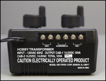
The accessory output is exactly 14.8 V AC RMS, just like the box says. My scope shows that it’s a clean sine wave, not an artificially-generated waveform.
The two “cab” outputs match up with the knobs on the front, so “cab 1” is for the left (as the operator faces it) throttle.
Slow Speed Running
This is the critical point: how does it compare to the Kato in making a loco move slowly? Surprisingly, they’re about the same, although the tech 7 has a very slight advantage. Running my Atlas B23 on the test track, both could make the model crawl. The Kato’s lowest speed that wasn’t jerky was 5.0 scale km/h (3.1 mph), while the Tech 7 could do about 4.8 scale km/h (3.0 mph). The tech 7 could go even slower, although the engine would pause briefly at times, putting in a scale 3.2 km/h (2.0 mph). Note that at these speeds, it takes 20 or more seconds to traverse a single 186 mm (7 5/8”) section of straight track. The interesting thing is that both packs were at about the 30% throttle setting for this, so there’s the potential for an even slower speed with a very good model.
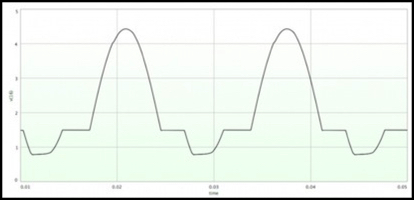
The scope shows that the output is a rather oddly-shaped waveform. The output fluctuates atop an offset, looking like some kind of step pyramid. At higher settings, the top of the peaks is clipped flat as well. The frequency is the usual 60 Hz wall-power frequency, the same as essentially every other power pack out there that does any kind of pulsing.
What this does is give a peak 3.9V signal to overcome any static friction, with an average power level of 2.4 Volts to run the train (assuming the scope is accurately calculating RMS voltage for a waveform this non-standard). The waveform changes as you turn up the throttle, but we’ll get to that in the next section.
Worth noting here is that both the Kato and the MRC are doing a form of “pulsed” power at an effective 120 Hz frequency, and both are using non-square waves. These are all good things. Although the frequency might not be ideal (that depends on a number of factors), it’s a common one in power packs.
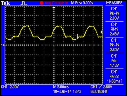
Tech 7 780 at 27% throttle (dead slow), 1.1V DC plus 2.8V wave, for 2.4V RMS
High Power, High Speed
So what happens when you turn up the juice? With an unloaded single loco, power gradually rises to 13.8 V RMS, with the fluctuations much reduced (the peak is about 14 volts, so it’s about +/- 0.2V of fluctuation). At full power, the scale speed of the loco is 198 km/h (123 mph). Since the Kato pack goes to a higher voltage, it has a slightly higher top speed (223 km/h, 139 mph). But really, I think that’s a bit higher voltage than I’d want to use. The MRC is definitely better, in the sense of: “isn’t as likely to harm anything”.
As you go up from 30% to 100%, the base DC voltage increases, and the amount of the fluctuation gets smaller. At the same time, the “step” portion moves up from near the low end of the pulse to near the top, helping to raise the average power level. Even at maximum, the fluctuation hasn’t entirely gone away, but it’s very small.
I need to do some testing with a real train to see how these work under load, but that will be a post for another day, as I haven’t gotten around to that testing just yet.
Update: I haven’t done load testing yet, but I have tested more using my track and comparing with the Kato pack. Speed at 12.0 V (as indicated on an RRampMeter, which means it’s trying to estimate RMS voltage) was about 15% faster for the MRC pack than the Kato. This may in part be due to the meter not doing a great job calculating RMS. Speed at peak voltage on the MRC, which the meter read as 13.3 V, was almost identical to the Kato’s speed at the same indicated voltage. I’m not really sure what to make of that, other than that in practice, the two are very similar in high-speed performance.
Circuitry
I’m a fairly curious fellow, and this time MRC used ordinary security screws (the kind that use a two-pronged screwdriver), so I was able to open the case. I was somewhat surprised by what I found. Inside is a very large, heavy transformer with two sets of output wires, and a large sheet-metal heat sink. There’s heat-sink compound between the power transistors and the heat sink; a nice touch. The build quality was certainly as expected. Everything’s firmly fixed in place, and hot-melt glue was used in a few places to reinforce things.
There’s one circuit board, and everything mounts to it except the transformer, master power switch, and output terminals (which have a small board of their own). The circuitry is basically two identical and separate circuits sharing the transformer and master switch.
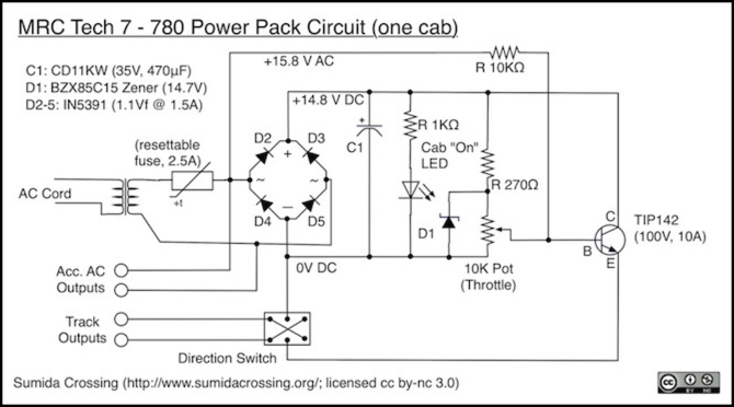
There are two separate diode bridges to rectify the AC to DC, and the “automatic circuit protector”, which appears to be a “polyswitch” device (Raychem RXEF 250, I think) rated for 2.5A, is also separate for each cab, so a short on one cab won’t affect operation of the other. The accessory output appears to directly tap off he transformer outputs, although downstream of one of the polyswitches (so a short on the accessories will affect Cab 1, and vice versa).
But that circuitry? I was expecting a microprocessor. What I found was an ordinary, well somewhat ordinary, transistor throttle, very similar to the one in the Kato pack, although perhaps somewhat higher-spec and with a little bit extra. The power transistor is a TIP142, which appears to be rated for 100V and 10A, well beyond what it needs to be. Overall the component selection has that “more than we really needed” feel that separates well-made gear from economy products.
Interestingly, the only patent listed on the box (which applies to “selected MRC throttles) is for a circuit with a microprocessor, and the manual doesn’t mention any patents. If this circuit is patented, they’ve forgotten to mention it. As I’ll mention in a bit, that’s likely because this is a very old design at heart.
Note: I’m not absolutely certain the potentiometer is 10K. I think it is, based on some multimeter measurements, but there’s no marking on it that I can see, and I’m measuring it in circuit, so I may have been getting a misleading reading.
The Clever Bits
Clearly there’s more going on here than in the Kato, given the waveform shown on the oscilloscope. But it’s nothing anywhere near as high-tech as a DCC decoder’s control circuitry. I can’t help feeling a bit let down. Sometimes it doesn’t pay to peer behind the magician’s curtain. And yet, I’m also very impressed with how much they’ve done with so few components.
On the DC side of the rectifier, things look fairly normal. There’s capacitor C1 to smooth the output, and a resistor/LED combo to provide a “yes the power is on” indicator (which goes off if the circuit protector trips). And there’s a power transistor driving the output, with a potentiometer to control it. But wait, what are these two other things?
First, there’s a link feeding AC into the “base” side of the transistor, with a 10K resistor to reduce its voltage. And second there’s this funny-looking diode wired backwards. It took me a while, and several simulations using SPICE to figure these out, because I kept seeing what I wanted to see, like not believing the AC could possibly connect to the transistor’s base. Once I finally figured out the right circuit diagram, and simulated it, things made sense.
The C1 capacitor is there to smooth the output of the rectifier, although simulating it with SPICE shows that it doesn’t entirely smooth the output, which is how we end up with pulses atop a DC base voltage. The “funny diode” in the glass case, D1, is a Zener diode, used to form a “clipper” circuit: it’s there to limit the output voltage, but it’s not limiting the output directly, but rather the control signal to the transistor. If the control voltage (output of the potentiometer plus the AC) exceeds the Zener’s rating (nominally 14.7 volts) it shuts down the transistor, effectively clipping off the top of the waveform at higher voltages.
But here’s the clever bit: by feeding in a reduced AC signal, they’ve modified the output of the potentiometer. The zener, working normally, allows the reverse current to flow for half of the wave, which is likely good for the circuit. But on the positive side of the wave, the AC component is added to the DC from the potentiometer. The AC will be relatively large when the throttle is low (small voltage coming from the potentiometer), and relatively small as it nears full throttle. This causes the transistor’s output to vary over the course of a 60Hz AC cycle, while the amount of variation is reduced as the throttle is turned up.
Effectively, the throttle is turned off for part of the cycle, rather than merely going low. But because there’s a model train connected, and current continues to flow in the motor, this tends to hold the voltage up slightly. Thus the “off” part of the cycle causes the voltage level to dip, but not entirely drop to zero (I should mention that my simulations included a train motor bases on some typical numbers I’d measured in the past).
Here’s a SPICE simulation at 30% throttle, look familiar?
Simulated circuit at 30% throttle
Now as it turns out, feeding in AC like this isn’t a new idea. I have a book on transistor throttle design from 1975 that shows a similar method to producing pulsed power, although the circuit wasn’t the same (possibly because silicon components back then weren’t as capable of handing high currents as they are today).
I am a bit concerned by the circuit interrupter. If I’ve read the specs right, it’s going to be slow to trip (seconds) and let a fairly large amount of current through before it does (2.5A at room temperature, less if it’s warm inside the case, which it likely will be). Since this is DC, rather than DCC, that’s probably not a serious problem. But I’d be happier with more aggressive protection.
Summary
The MRC Tech 7 780 looks to be a good N-scale power pack. It wouldn’t be bad for HO either, although slightly underpowered in terms of VA for more demanding applications, like sound. Its maximum voltage is slightly less than Kato’s, and closer to the nominal N-scale level, and at higher throttle settings the output is more like DC than the Kato’s output. Its power output, at a nominal 700 mA, is also somewhat less than Kato’s 1,000 mA, although I suspect it’s been rated conservatively and can produce much more.
If it really is limited to 700 mA somehow, that would be good. It’s ultimately current that damages motors, and 700 mA is more than enough to run two N-scale locos double-heading a large freight or a long Shinkansen. I don’t need more.
However, you might. Some N-scale models need more power. I have a Kato N-scale SD80 with a stall current of 1 amp at 12 volts (which means about 1.2 amps at 15 volts), and while normally it would draw a lot less, if you really pushed it to the limit with a heavy train this pack might not be adequate. If you do N-scale with sound, it’s also possible that you would need more. N lacks space for a large speaker, which is what consumes the power, so it could be fine. But I don’t have any experience with N-scale sound systems, so I couldn’t say what’s needed. Still for me, most of my motors seem to have limits around a few hundred milliamps, so even with a two-motor train (some of my models have two motors) I expect 700 mA to be adequate.
At the low end, it’s perhaps a hair better than Kato’s in terms of slow running, although not as much as I’d have expected. Kato has the edge in the ergonomics (human friendliness) of its controls, with the large direction lever with a neutral position, and its larger throttle knob, but it’s not a substantial advantage.
And if you’re doing double-track and need two power packs, there’s a significant cost-savings in the MRC over a pair of Kato packs, assuming you shop around for a good price. Neither has any fancy features like momentum or braking controls, but if you want that level of sophistication you’d be much better off with DCC anyway.
One thing to point out: I don’t run with common-rail wiring, but many multi-block, multi-cab layouts do. Neither the box nor the manual included mention common rail, but the website where I bought it did, claiming it was “designed” for such use. From the circuit diagram I can see that there’s nothing protecting the transistor from reversed current (the zener doesn’t appear to be in the right place to do so). And that’s something you can get in some kinds of common-rail failures. And from the spec sheet, I know that transistor has a limit of 5V of emitter-base current. It would thus appear to be possible to blow the transistor in some kinds of common-rail failures, if the other pack doesn’t shut down quickly enough. Something to consider before using one of these in such an environment.
I’m a bit disappointed to find that what’s inside the case is so simple. The build quality was very high, but the circuitry, while clever, was more simplistic than I expected. On the other hand, that does explain why the performance is similar to that of Kato’s product: at starting voltage, the two output nearly the same thing. MRC’s output waveform, both near-DC at higher voltages and clipped ripple at lower voltages, is probably a bit gentler on the motor, although I don’t think Kato’s is going to be harmful.
Bottom line: it’s not ideal, but I think it represents an improvement over the current Kato power packs, so this is getting wired to my Express line and will be used for DC operation on the layout, which includes breaking in new models and running things I haven’t yet converted to DCC. The two Kato packs currently in use get retired, as least until I need another N-scale pack for something (my third Kato pack is permanently assigned to my workbench).