


Going Around the Wall
05 July 2014 23:41 Filed in: Design,Construction
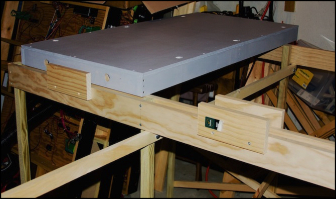
Sumida Crossing’s benchwork - free-floating 24” x 48” tables resting on support girders
Benchwork is fundamental to a model railroad. It provides the structure that ties everything together, and over the long term dictates what can and cannot be done. While I created Sumida Crossing, I was intent on recreating the “tabletop” approach I’d used on the Kitchen Table Layout, but as a sectional layout with permanent scenery, something that would hold up well to moves.
To do that I created “box” tables using 2 foot by 4 foot 1/2” plywood panels (30 cm x 60 cm, 12mm) on 1x3 sides (12 mm x 75 mm). These were solid (I could stand on them) but heavy, although they were easy to move even once I added scenery. Putting a backdrop on one, however, made them very hard to move, so they’re really only “portable” if I unbolt the backdrop (I used bolts for all non-permanent connections). Those table rested atop an open-frame structure made of 1x3 and 1x4 pine boards and 2x2 posts for legs. Leveling feet were on the end of each leg, so the upper surface was flat despite irregularities in the floor. The frame was made of flat sections bolted to cross braces, so it could easily come apart and fit in a van or on the roof of a car.
That worked, but it was inflexible in several ways. I couldn’t go “below ground” easily, so extra foam above the table needed to be added to create space for a subway and below-ground river surfaces, and this put the river really lower than I wanted it. It also meant that the subway couldn’t easily cross under a river. Further, the heavy box-structure “tables” with multiple inches of foam above them made dropping wires for building lighting, track switches (turnouts) or track power problematic. And lastly, the frame supports stuck out several inches past the front of the layout, and over time that really came to annoy me.
I did like the height (48” to typical “ground”, about 122 cm). It was a good viewing height for me (I’m just under 6’ or about 182 cm, tall), and also provided clearance below so I could sit on the floor when working below the layout. However, putting wiring on the underside of the tables meant I was reaching up to work on it, which was hard on both neck and arms when done for extended periods.
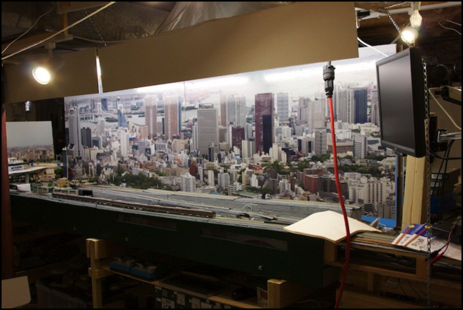
Riverside Scene with chain-hung lighting valences (and old track lighting)
When I did the fluorescent lighting modules for the Riverside Station scene, they worked well and I liked the overall effect of having a lighting valence with tube fluorescents, but using one suspended by chains was problematic. A more rigid structure was needed for that.
Backdrop design is also a concern. I’d started with backdrops 18 inches (46 cm) in height left over from my old HO layout. There they’d just been painted blue, and worked okay, but with photographs that was really too short. I used 24” (61 cm) for the River Crossing scene, and that worked well, although I ended up with a lot of open sky at the top due to the photo I’d used. When I created the backdrops for the Urban and Riverside scenes I made a mistake when creating the (very expensive) print, and needed to extend the backdrop to 29” (74 cm) to fit them. That was really too big, and the photo’s tended to dominate the Riverside scene. They worked better on the Urban Scene, but were still rather large.
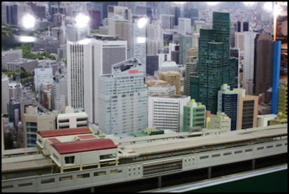
Urban Scene backdrop - with glare from original track lighting spotlights
My conclusion is that I need to work with backdrops around 20 - 24 inches in height (50 - 60 cm), and that I also need the valences to hide glare from the lighting against the top of the image. Assuming that scenery will rise in some places (low hills), the backdrop probably needs to be at the high end of that range in overall height.
One other aspect to consider is that with a lighting valence, I won’t actually see the top of the backdrop most of the time (although children and short adults would), so I should plan to have the actual image of interest somewhat shorter than the backdrop. So this could mean photos with buildings no more than about 18” high on a 24” backdrop (for example).
Those could be 24” high photos with sky at the top, or I could work with shorter photos on that size backdrop, with blue paint for the sky above them, and this might also help avoid the glare off the glossy photos (or I could experiment with matt-finish photos, although I don’t think those would look very real). I have more work to do with backdrop design, but for now at least I have a desired size to plan to.
Sumida Crossing was built with tables 24” (61 cm) deep from front edge to backdrop. This was partly because the old HO layout had been 30” (76 cm) deep, and I’d had problems reaching the back to work on it, and partly because of room constraints that made anything in the middle of the room wider than twice 24” impractical (there were support posts in the way).
I found 24” to be a workable depth. It’s easy to reach the back to make changes, although it can be more difficult if there is higher scenery in the foreground you have to reach over. And it’s sufficient for a couple of double-track lines and some scenery (or a six-track station with very little scenery). I’d probably want to go wider for a storage yard, although reach has to be considered there too. And I could go narrower for a simple “track running past scenery” scene. But a typical depth of 24” seems like a good average size. That’s important for planning, since I need to fit both layout and sufficient aisles into a fixed amount of space.
My current aisle on one side of the layout is about 30” at its widest, and in several places it’s narrower. I find myself mostly working in the wide portion, and even that is cramped with a visitor. I’m going to plan for 36” typical aisle spacing to allow two people to pass comfortably, and even more in places where I’d expect people to gather if I have guests. I might allow narrower aisles in some places, but one thing I want to consider is wheelchair access, and 36” is really the minimum width for that (and more is needed at the ends of aisle for turning).
That gives me a basic set of dimensions:
Track to Floor: 48” / 122 cm (typical, will vary)
Under-table clearance: 40” / 102 cm (can be slightly lower if needed)
Backdrop scenery-to-top: 24” / 61 cm (maximum)
Layout Depth (front to back): 24” / 61 cm (average)
Aisle width: 36” / 91 cm typical minimum
That will all fit in a little over 6’ (183 cm) of vertical space, and any beams lower than that can be worked around with a break in the lighting valence.
My last problem was that building the layout as two back-to-back sections with a divider between them was efficient of space, but it led to me tending to ignore the “far side” of the layout, and just stay in one place while operating trains. An around-the-wall layout puts the operator in the middle, although with a large enough railroad (e.g., with a peninsula in a large room) you can end up with different areas much the same as with my island design. Still, my thoughts now are leaning towards an around-the-room design.
Over the years I’ve read a number of articles about such layouts, and how to build them. The use of L-girder supporting structures is well-proven by decades of use. Several recent designs I’ve read about essentially cantilever the layout off a wall (or off supports against a wall), leaving space under the front of the layout clear. This strikes me as practical in several ways: it provides ease of access to the underside, a place where portable storage (e.g., rolling cabinets) can be kept, and it avoids the problem of banging knees against legs at the edge of the layout (I’m a klutz; I’ve done that too many times to count).
Note that the wall is not necessarily the support. Those vertical boards against the wall could be attached to the joists overhead (given a basement with an open ceiling, which I have), making the floor above the actual support. This is particularly advantageous when creating a free-standing peninsula in the middle of a room.
So here’s what I’m presently thinking of as a structure:
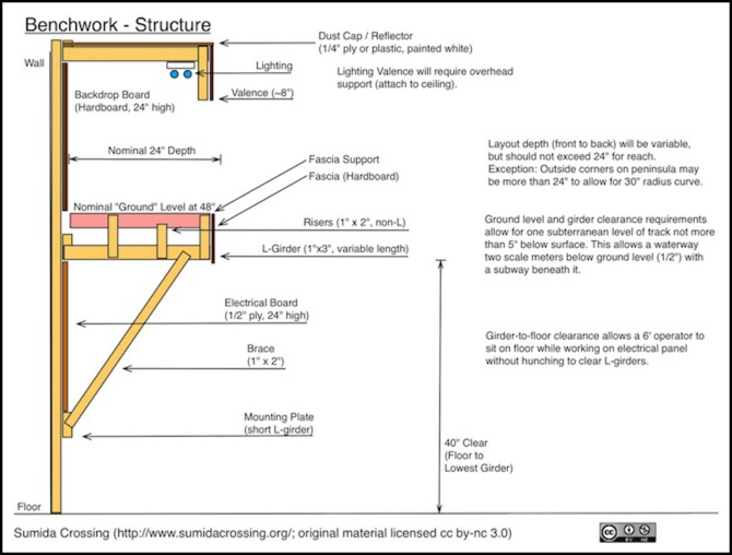
This is, of course, still very preliminary. But so far, it ticks all the boxes on my list of desired features. There’s room to work, room for a subway, space for a backdrop of about 24” (60 cm) in height, which I think is the right size. The one downside is that this height works well for a standing adult (even one shorter than me), but it may be too high for smaller children, and it’s definitely too high for someone in a wheelchair.
That last could be addressed by raising the floor in the aisle, which I’ve seen done when layouts were multi-level, to put eyes at the same height for each level. I don’t presently have a requirement for wheelchair accessibility, but if I’m going to plan for the long term, I really ought to consider that. Twenty years from now I could be in one, or have a friend who is. I suspect I’ll use this height, and keep the “raised aisle” as a contingency plan for future use if needed, but I need to think on that some more.
The hidden downside of an around-the-wall design is that I lose portability. But moves are less likely now, and I don’t expect to have to move this layout. If I do, the backdrop, lighting, and structures are all portable. Even the valence and fascia could come off. And in fact the big electrical boards could be unscrewed and moved. What I’d likely lose are the L-girders, track and any “ground” scenery, but that’s relatively easy to re-create (well, the track would be a bit of work). I could even make the scenery sectional, but I think in doing that I’d end up with something less flexible (like my current layout), and I don’t think it’s worth that cost.
The other thing related to the benchwork is where I put the electrical stuff. In Sumida Crossing, the original plan was to install it on the underside of the tables. This failed for a number of reasons: chiefly that there wasn’t enough space, and also that access once the table was installed became extremely awkward. Attempt two put the electronics on fold-down boards, which worked better, but added complexity to the wiring to allow the boards to be removed (even hinged, they were still hard to work on in place).
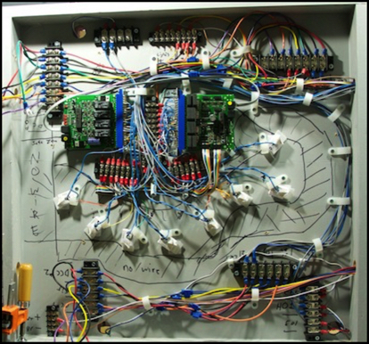
How NOT to install wiring - 2’ x 2’ under-table space with PM42 & BDL168
My current idea is to put this all on a board against the wall below the layout (seen in benchwork diagram above). This will be easily accessible when sitting on the floor under the layout, yet far enough from the aisle to avoid being hit. It also allows for lots of space to put things. I’d probably use 2’ x 4’ panels of 1/2” plywood to make these, to avoid any extra cutting of wood or odd-shaped scraps, so that gives me a full 2’ of vertical space on which to mount things. Using 1/2” plywood gives enough depth for screws to hold things to the wood securely.
I’m also rethinking the power bus design I used for 12V lighting and 15V accessory power. While putting in lots of small 100 mA “wall wart” transformers instead of one big 2 Amp power supply is inefficient in a sense (and more expensive) it’s also more modular, meaning easy to expand and troubleshoot. I’m leaning to a set of switched AC power strips under the layout, with most things powered off small wall-warts. When I’m not using the layout, I just turn off one switch and all the wall-warts power off.
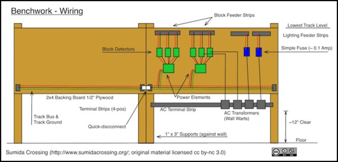
So this gives me something like the above. Track would have short feeders to terminal strips directly below the track, mounted on risers or the underside of plywood subroadbed. From there, heavier-gauge wires would run down to “block feeder strips” on the boards shown here (with potentially several feeders in one block connected with one multi-drop wire to the block feeder strip). Each block would have a small occupancy detector (I’m thinking of the simple inductive-coil kind) and a set of blocks on one line would have a circuit breaker (multiple lines means multiple circuit breakers so a derailment on one doesn’t power the whole section down).
Feeding the occupancy detectors would be something that provided protection (the “Power Element” in the above diagram). This could be a simple DCC circuit breaker connected to a track bus (red/black/green wires), or it could be a small (~3A) DCC booster connected to a +15V supply line. The latter would be overkill in terms of available power for trains I’m likely to run now, but I like the idea of distributing the power supply, as it provides lots of headroom for future growth (i.e., sound decoders in trains).
Note: not shown above is a control and/or feedback bus, which I need to add.
Separately, lighting and other DC accessories would have individual wall warts as needed, with small inline fuses (automobile fuses) as local protection.
Things could easily be debugged by unscrewing terminal strip wires in plain sight, or replacing wall-warts.
This seems to give me what I want. Flexible benchwork that’s easily customized to vary the height of track and scenery, to add in one level of underground track, or to vary the width of the layout, and lots of room for easily-accessible electronics under the layout, with modularity there to improve the ability to quickly isolate problems. It does assume DCC (you’ll note that there’s no provision for DC track power here), which I need to think on some more. But ultimately going “all in” on DCC makes the most sense. Mixed DC/DCC wiring is problematic, and just gives me an excuse not to convert trains.