


Transition Curves and Superelevation
All of my Japanese-themed layouts to date have used sectional track, either Kato Unitrack or Tomix Finetrack. I haven’t built a layout using flex track in more than twenty years. And that layout was a relatively simple one, modeling an American freight shortline, with low-speed trains and no “mainline” trackage. That let me cut a few corners.
But now that I’m thinking of building a new layout using flex track, and particularly one with mainline track for both moderate-speed commuter and high-speed Shinkansen, it’s time for me to confront two of the more complicated aspects of trackwork that I’ve so far been able to avoid: transition curves and superelevation (for more information on these, see my Easements page). And it turns out, neither is really complicated after all.
Transition curves, also known as easement curves, spiral easements, or just easements, are a means of making the transition from straight track to curved track more gentle. On the prototype they’re vital even at moderate speeds of 30 mph (~50 kph), and even more so for high-speed rail. Even for modeling, they are important not simply for capturing the look of the prototype, but also for operational reasons. On tight curves, they make long cars less likely to bind where they couple, and at higher speeds just as on the prototype they avoid sharp sideways jerks as trains enter and leave curves that would make derailments more likely.
Superelevation, also known as “cant” or “banked” track, is merely cosmetic on a model railroad, although it serves a vital purpose on the prototype. But it’s a cosmetic touch that’s important in recreating the look of modern mainline action. It’s so important that even sectional track like Unitrack now comes with banked curves.
Kato’s banked Unitrack curves have an outer rail raised 140 scale mm (5.5 scale inches) above the inner. That’s close to the maximum you’ll find on all but dedicated high-speed rail lines. The maximum amount of cant is limited because trains still need to be able to move at slower speeds, and too much cant can be as problematic as too little. Broad curves used at lower speeds also require less cant than sharper ones or ones used at higher speeds.
Creating banked flex track is very simple, and I’ll come back to that in a bit: but first, easements. When I first planned that old HO layout years ago, I read up on this. Primary among my reading back then was the NMRA’s Data Sheet D3b (only available to members), which covers both superelevation and easements. It has a good basic description of the purpose of both, and then tries to describe a simplified system for selecting an easement. Unfortunately it fails at “simplified” so badly that I was never able to make sense of the explanation. Even today, knowing much more about the topic, I can’t understand the charts they provide for calculating easement dimensions.
At the time, I just threw up my hands and said “I don’t need this on a freight shortline” and gave up. I don’t have that luxury today. Fortunately we have the Internet and Google now, so it’s a lot easier to find reference information and explanations of the math involved. Easements require wading through a lot of math if you want to really understand them, although you don’t actually NEED to do the math to build them. I’m plagued by the need to understand things, though.
And having fought my way through the math and looked at the methods normally used by modelers I’ve realized something very important: model railroad easements are trivially easy to do. You don’t need math or exact formulas. You certainly don’t need the NMRA’s opaque set of diagrams. You just need a couple of basic bits of info, some rough dimensions for your scale, and you’re nearly done before you start. They’re that simple.
Easements
The theory of an easement curve is easy to state: it’s a curve that starts out in line with straight track and smoothly changes its radius from infinite (straight) until it gets to the same radius as the curve it’s connecting to, at which point it blends seamlessly into the curved track that has a fixed radius. An easement needs to be longer than the longest car using it (a good rule of thumb is 1.5 car lengths), and the section of simply-curved track between the easements at each end needs to be several carlengths long if it’s going to look good.
You’ll note that those requirements mean easements aren’t going to work very well with short, sharp curves. But you don’t need an easement on yard or industrial track with curves less than one car long used by short cars and small locos, or even a weed-strewn branch that trains trundle down slowly, although you may want to use a small easement on sharp curves for operational, not visual, reasons. You mostly need it on mainlines (or branch lines operated at moderately high speed). If you aren’t using fairly broad curves on a mainline, you have worse problems than the lack of easements.
The late John Armstrong, in his book Track Planning for Realistic Operation (3rd Ed., Kalmbach, 1998), laid out a simple approach to doing easements on a model railroad. Armstrong, in addition to being a prolific model railroad author noted for his track plans, was also a skilled mechanical engineer who had reported on prototype railroad technology for many years. He knew what he was talking about when it came to easements, and he had the skill to communicate it well. His book doesn’t say a lot about easements, merely fitting it into a sidebar on one page, but it says all that really needs to be said, clearly. It’s well worth reading. The method used to create easements in XTrkCad was clearly influenced by his approach.
One problem with easements is that they take up space. It’s not a lot of space, typically side-to-side in N-scale you’re going to add about a half an inch to 3/4 of an inch (one to two centimeters) to the overall width of a 180-degree curve. Lengthwise they take more space, perhaps 8-11 inches (20 - 28 cm), however about half of that overlaps with the curve. So on a broad 22-inch radius (550 mm) curve, you’re adding about 20% to the lengthwise space. Still, most model railroads are starved for space as it is, so this is something you have to really want. One saving grace is that easements let you reduce the radius somewhat and get similarly reliable operation (although visually it may not be as good).
This all means that planning for easements needs to be done very early on, to make sure there is room to build them and still have the curve be as broad as desired for other reasons (like reliable operation of long cars).
I won’t go into the math here (see the Easements page for that), but real railroads typically approximate the ideal easement curve with something called a spiral, which is described by a cubic polynomial. That sounds complex, but it’s easier to deal with than the ideal. Spirals are a well-known engineering technique, used to construct highway on-ramps and roller-coaster loops. There are books with tables that define the proper shape of easement curves for a variety of situations. And today there’s software too. While railway engineers use complex CAD software, modelers can do the same thing with XTrkCad (which lets you create broad, normal and sharp easements).
You can calculate a good (prototype) easement from the radius of the curve and the speed of the train. However, this is a place where selective compression comes into play on a model. Just as our curves are much sharper than prototype curves would really be, we can get away with shorter easements that will still function and look good.
So you don’t actually need any of that math.
An easement curve can be created with a variety of lengths and widths. The length is the most important criteria, and on the prototype is dictated by the maximum allowed change in sideways acceleration that passengers (or top-heavy cars) will tolerate. This means that as speeds go up, or curves become sharper, the easements must become longer to keep the sideways lurch of the train to the same limits.
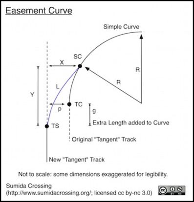
In N-scale a model easement is going to have a length (Y in the diagram above) around 150 mm to 200 mm (6” to 8”) as measured along the line passing through TS in the diagram above, from TS to a point parallel to point SC, with point TC at the midpoint. In other words, you’re adding 75 to 100 mm to the space occupied by the curve in that direction.
Note: for all practical modeling purposes, Y = L, so often L is used to designate the length along the straight line. In a real easement, L is the length along the curving track itself.
And the additional sideways space, or offset (“p” in the diagram) is around 4 to 10 mm. Pick an appropriate length and offset based on the curve you’re using. It doesn’t need to be exact. In fact, there’s no “right” answer in this case. Y=200 mm and p=10 mm is likely to be quite enough for even the broadest curves.
There is a lot of guidance on what to use on model railroads (and I summarized that on my Easements page), and you can find much of it simply by googling around, but ultimately it comes down to personal taste. It may be best to build a temporary loop with a couple of different easements on curves, and see how the running trains look to you, before committing to a specific dimension for permanent construction. I’ll probably do that eventually, but I’m not ready for that yet. But even that may not be needed.
Once you have those two dimensions, length Y and offset p, select points TS and SC in the diagram above such that lengths g is 1/2 Y, and p is your offset, and then use the “bent stick” method to draw a line from point TS to point SC that is exactly aligned with the track at both points.
The bent stick method is based on the fact that a flexible but springy object that is held straight at both ends will naturally curve into an approximation of a spiral curve. So take a flexible metal ruler or similar, stand it on edge, hold one end so it runs along the straight track at TS (and keep it pinned at TS) and bend it sideways until it meets the curved line end-on at point SC. Then trace the line of the ruler, and you’ll have your spiral. Yes, you need three hands for this, or a friend, or some way to clamp one end of the “stick” in place. But that’s it.
And now you’ve just designed an easement without using any math except dividing by two. Easy, wasn’t it?
Superelevation
Unlike easements, superelevation serves no functional purpose on a model railroad, it is purely visual. There are no passengers to adversely affect, nor is rail or wheel wear a concern. And the masses and speeds involved pose no risk of overturning at any prototypical speed (including that of Shinkansen).
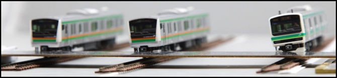
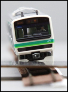
The photos below, along with the photo at the top of the post, show three of my commuter cab cars posed on track that’s been superelevated by placing shims below the rail on the right. On the left is the uncanted view. In the middle, 0.025” of shim has been added, producing a scale cant of 65 mm (2.5”), while on the right 0.055” of shim have been added, producing a scale cant of 143 mm (5.7”). The photo at the top of the page shows the same.
Note that the cant is smaller than the shim thickness because both rails are raised relative to the end of the tie that remains on the “ground”.
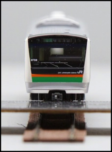
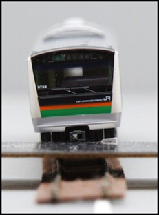
No, moderate and full cant on Micro Engineering Code 55 track
As you can see, even a relatively small cant is fairly visible. From several feet the middle one is quite subtle, but there, while the far right one is very obvious. This confirms my hunch that I’d want to use a more subtle cant (about that given in the middle, or perhaps slightly more) for a typical curve, and save the large cant for use on Shinkansen lines, if at all.
Even there, while the right-hand photo has almost exactly the same cant as Kato’s banked Unitrack, it looks excessive, particularly for these models. I’m likely to use a somewhat reduced degree of cant even for the Shinkansen track.
When creating canted track, you need a section that adapts from no cant to the full amount at the beginning and end of the curve. This doesn’t have to be very long, and most references I’ve seen suggest using the length of the easement to perform the adaptation, so that the cant increases as the radius of curvature gets smaller.
Summary
I’d been dreading dealing with easements, and expecting I’d have to build a fancy spreadsheet to work them out for all of the various curves I was going to have, since things like a four-track main weren’t likely to fit into the “three curves” model used by XTrkCad even if I wanted to use that software.
But the reality is that what XTrkCad is doing (and John Armstrong’s method on which it is based) is simply giving you a three-way choice of space-saving versus good-looking curves. And you (and I) can just as easily pick others on the same approximate scale.
Superelevation is similarly simple, and ultimately both are driven more by visual criteria than anything else. I expect I’ll ultimately build some test track to validate my ideas before I start cutting plywood to lay subroadbed, but I’m fairly sure they’re right. This is all much less of a bother than I’d been thinking it would be.