


LCC II - How It Works - Physical
This is the second in a series of posts on the NMRA's new Layout Command Control (LCC) standards. The first post covered the reasons why a control bus, and specifically LCC, were important, as well as providing a fairly high-level view of how LCC works. Today we'll get into some very specific details regarding the physical aspects of the network, specifically the CAN Bus wiring and usage. Next time, I'll cover the actual messaging on the network (i.e., what you can do with it).
In reading the standards I had a number of "Why did they say that?" moments, where I had to spend some time thinking and doing other reading to try to grasp why what looked like, at first glance, to be a mistake turned out to have some sense behind it. In some cases, it's simply a matter of there being more than one valid approach. In others, what looks wrong is almost certainly a good compromise where there is no complete solution to all of the requirements.
I'm not saying the physical aspect of the LCC standards is perfect. But some of the issues are based on how CAN Bus does things, and that's worked for 25+ years, so not only can't LCC change those parts, it doesn't seem like it needs to. Others appear to be compromises made to keep costs lower, and those too have their roots in existing CAN Bus design. The end result seems to me to be a good design for the first LCC physical layer.
Some aspects of it I really like: the use of RJ45 connectors and standard Ethernet cable, for example. Never re-invent the wheel if you don't need to, and the RJ45 is one of the most reliable data-communications connectors ever made. Plus it's inexpensive. As we’ll see, LCC didn’t invent this cabling option for CAN Bus, they adopted it from a fifteen-year-old factory automation network design that uses CAN Bus. Another example of sensible re-use of existing designs.
Another aspect I liked is the modern approach to network design. This means logically subdividing the network into “layers”, with the physical layer providing a foundation. The “data link” layer goes along with the physical, and defines how higher layers use it. And because of that, different physical layers (like wireless) can be swapped in as long as a new data link layer is defined. Physical layers for LCC are likely to be pre-existing technologies (like CAN Bus, Wi-Fi or Bluetooth), so this makes it really easy for LCC to add new connectivity capabilities in the future.
CAN Bus itself is a good choice. Modern technology implements the bus support in (typically) a pair of chips, total cost under US$5 per node. That needs to be paired with a processor, but those only cost a few dollars now, and most nodes would probably use one anyway. It’s going to be a fairly economical approach, and has more than enough capacity and flexibility for our needs.
Still, I had a lot of questions, and this post reflects what I dug into during and after reading the standards as I worked through those questions and my own set of answers. Buried in here is also a collection of what I'll eventually collect on some other page as "LCC Wiring Guidelines"; my interpretation of what matters when cabling up nodes.
I'll try to keep this relatively simple, but I want to explain some of the "why" as well as the "how" so I'll get a bit detailed in places. Feel free to skim over the deep stuff if it isn't making sense; it's not essential.
As usual, a caveat: I'm not an expert in CAN Bus networks or LCC (is anyone an expert in LCC yet?). I'm a hobbyist. I have a slight advantage in reading these standards in that in my day job, I am a network engineer and I've been reading similar documents for decades. But I don't normally work with automation systems or CAN networks, so there's still room for me to misunderstand or otherwise get things wrong. And nothing in this post (or any of my posts) should be taken as professional advice. Use at your own risk, as always.
LCC Networks
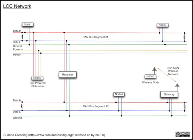
The diagram at the top of this post shows a fairly complex LCC network, although with only a few nodes. It has one CAN Bus segment with the optional power wires, allowing bus-powered nodes (e.g., Node2). This could be something like a hand-held throttle on a short tether cable plugged into a fascia panel. The diagram also shows a second bus (we'll get to why you'd want two down in the Repeaters section) without the optional wires, and a gateway to a wireless network, which might be used for radio-connected walkaround throttles. Note that I've drawn the ground as a single wire, because even though there are two wires they are used as if they were one (more on that in the Grounding section).
At present, we can't build much of an LCC network, as there aren't any LCC products on the market, aside from some demonstration devices produced a couple of years ago, most no longer available. There's a library that would let you make your own node with an Arduino and a shield, if you were into that kind of do-it-yourself approach, but it's the demo library from three years ago, and somewhat lacking (a fact its own documentation admits). Someone's going to need to do a real LCC library for Arduino before it's going to attract a lot of hobbyist attention.
LCC will certainly be much easier to understand once we have people selling equipment (and having to write explanations of how to install it), but for now to understand what an LCC network will look like, we have to turn to the standards.
NMRA Standards
Of course, almost all of this comes from the NMRA standards, S-9.7.x: Layout Command Control (LCC) - OpenLCB. Much of what I'm saying in today's post, although not all, is essentially a paraphrase of portions of the NMRA documents.
Some of what the NMRA specifies is there because of limits imposed by other standards. Other parts reflect choices intended to make LCC appropriate for its intended role: linking devices used on a model railroad. That application has both cost and performance implications, which guide the choices made.
At present the LCC standards aren't complete: for example, they don't define how wireless would be done, and only talk briefly about LCC will use non-CAN networks. That's all planned, eventually, but for now we're a little more limited in what we can do. Note that I’m not going to get into anything from the under-development standards. That’s partly because they’re not yet adopted, so they could change, and I don’t have time to invest in reading a draft. It’s also because the OpenLCB website is riddled with broken links, and I don’t have copies of any of them to read.
The NMRA standards cover four broad areas:
- S-9.7.0.x: Information about events, identifiers and other aspects.
- S-9.7.1.x: The Physical Layer of the CAN bus network
- S-9.7.2.x: The Data Link Layer of the CAN Bus network
- S-9.7.3.x: How messages are sent across the network and related aspects
- S-9.7.4.x: The Session Layer, covering configuration and other details
Now if that all sounds a bit arcane, that's because it is. There's a specific vocabulary used to describe networks of communicating computers, which is what LCC is. The jargon and the division into those four major categories can be a bit impenetrable to someone outside the field, but it does make sense.
Today we're going to focus on standard S-9.7.1.1 and the accompanying technical note TN-9.7.1.1 (when I say "the CAN technical note" below, that's what I mean), which together tell us how to wire up a CAN Bus for LCC use. If you don't know what a CAN Bus is, or why you should care, I suggest reading last week's post, as it goes into that in detail.
Other Standards
Although the CAN Bus was originally developed for automobile use, it's been applied in a number of other areas, and there are numerous variants even for automobiles. The basic definition is a family of standards under the ISO 11898 grouping. But this provides for a large set of options, so any specific application will need to provide additional specifications, and this is what the NMRA's standards for LCC do.
There are also two other standards of interest. These are actually mentioned in the CAN technical note, although I overlooked one of them on the first couple of readings. It's worth taking a look at these, as material related to them may be helpful.
One obvious standard is the one for the actual cable used. This is generally described as "Ethernet cable", but that's based on TIA/EIA-568-B, a standard published jointly by the Telecommunications Industry Association (TIA) and Electronic Industries Alliance (EIA). Finding a copy may be difficult, as this body charges for its standards. All you really need to know about it though is that it defines the rules for how people make Ethernet cables and connectors, so when you buy a "Category 3 Ethernet cable", you ought to be getting something that will do what you need, regardless of who is selling it.
A good source of information about CAN is the CAN in Automation (CiA) group. This is a non-profit manufacturers alliance, and they produce standards for all kinds of CAN applications, under the name CANopen. This includes trucking, marine use (boat instrumentation), railroad locomotives, and factory automation. Unlike many other standards bodies they make their final documents available for free (if you register). Drafts are only available to paying members, but those aren't likely to be the ones we'd want.
One of their most interesting documents is CiA 303, CANopen Recommendation, Part 1: Cabling and connector pin assignment. This was first published in 1999, and revised multiple times since then. Beyond what the title says, this provides some useful information on the physical network design. Although LCC is not CANopen, the Ethernet cable pin assignments used in LCC come from it, and CANopen provides some guidance on network design that is applicable to LCC.
The CiA also publishes a quarterly newsletter, and in the current (September 2015) issue there's a short article on use of IP networks to carry CAN frames, which makes for interesting reading. And for the railfan, the September 2012 issue has three articles about use of CAN in real trains.
CAN Bus Physical Layer
Today, we'll focus on the physical layer, as defined in S-9.7.1.1. As the word suggests, this means the hardware elements of the system: the wires and connectors, and the rules for their use, such as maximum length and how they connect to each other and to devices. The data link portion is closely tied to this, as it specifies things like the voltage used over the wire and how data is structured (patterns of bits and the meaning applied to them).
We don't need to worry about voltage, as that's all handled by the hardware (the CAN transceiver, to be specific). But, for the curious, CAN uses two signals that differ by either less than a volt or just over two volts. The maximum voltage of the higher one is around 5.5 Volts. It does mean that the power supply would need to be higher than 5V though (one common transceiver chip uses 7V input power). This is why the optional power supply wires have a minimum voltage of 9V for "Power +" relative to "Power -".
In LCC today there is only one physical/data-link specification, which is based on the Controller Area Network Bus (CAN Bus). But because the important part is what messages mean, and that is separated out into the network/session portions, in the future we'll be able to swap out the physical/data-link for other forms, such as wireless. This will enable wired CAN Bus LCC nodes to communicate via wireless with other LCC nodes, and LCC across a radio link should behave exactly like LCC across a wire.
LCC Nodes and the CAN Bus
A CAN Bus network is nothing more than a collection of CAN Nodes wired together. A CAN Node is, at heart, a tiny computer plugged into a CAN Bus. For LCC this could be a signal mast, or a board with 16 I/O connections, or a USB adapter for a computer (well, technically the computer plus the adapter is the node), or it could be something else. But they all have several things in common, and up to a point they all behave the same way.
Each LCC CAN node will include a pair of RJ45 connectors wired back to back, so the bus is a contiguous bundle of eight (or four) wires from one end to the other. Each node will also have three functional elements: the Processor, Controller and Transceiver. In most cases these will be three separate integrated circuits (chips).
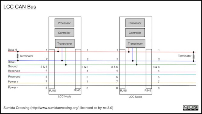
On a Node, at a minimum the Transceiver will connect to the CAN_H and CAN_L wires (also called "Data H" and "Data L"). It will also connect to the ground wire (which is really two wires, something we'll get to in the Grounding section). There are four other wires, two reserved for future use, and two used to deliver power to nodes small enough not to bother with their own supplies.
The Transceiver's job is to apply electricity to the bus, and to sense electricity from it. It's controlled, reasonably enough, by the Controller. A transceiver deals with one bit of data at a time. The Controller takes messages, breaks them up into bits, and uses the Transceiver to send them (or, in the reverse, it gets one bit at a time and assembles them into messages).
The Processor is the part that implements the complex aspects of the CAN Bus and LCC protocols (the rules for how they work) and also does whatever it is that the node actually does (senses trains in a block, lights signal lamps, etc). It creates new messages, or decides what to do with received ones. This is done with software, usually running on a microprocessor similar to the one used in an Arduino, but the software could be running on a general-purpose computer processor.
While requiring a microprocessor (and software for it) might sound very complicated for something like a model railroad signal mast, these days it’s not uncommon for fairly simple devices to contain microprocessors. They’re cheap and generally simpler to build circuits with than if you assembled a bunch of transistors and similar to do the same thing. And using CAN requires one, because part of the CAN protocol needs to be handled in a processor.
In a purpose-built node, all three chips will likely be on one board. On an Arduino, the basic Arduino board contains the processor (the Arduino itself) and a separate "Shield" board contains the Controller and Transceiver.
As you can see, the three modules have nothing to do with the "reserved" wires. And they don't really have anything to do with the two "Power" wires either, unless they are drawing power from them. You could make a node with just H, L and Ground, and the LCC standard allows this (using two wires for Ground, as we'll get to below).
CAN Bus for LCC
CAN Bus isn't a simple specification. While a number of aspects are standardized, these often have ranges of allowed definitions. The CAN Bus used by your car's On-Board Diagnostics (OBD) can be completely incompatible with the CAN Bus used in your neighbors car. Most OBD diagnostic tools have to support several different kinds of CAN Bus. And LCC has chosen yet another set of criteria. So something made for use with an OBD system may not be useful for LCC, although in theory a well-designed device should work for any CAN Bus network if you connect it properly.
LCC has standardized on a specific cable and connector system, and on a data rate of 125 Kbps (most car systems work at 500 Kbps). The wire used is "Ethernet" cable, meaning a bundle of twisted pairs that meet certain standards, and the connectors are RJ45 modular connectors, also used with Ethernet.
But don't confuse LCC (or CAN Bus) with Ethernet; the only thing they have in common is the wire. You won't be able to plug a computer's Ethernet jack into a CAN Bus, you'll need some kind of adapter (probably a USB-based device). Today there do not appear to be any LCC-compatible USB devices, at least none in production and with JMRI support. There are a few USB CAN interfaces designed for OBD use, often rather expensive.
The reason CAN is called a "Bus" is because the wire is actually continuous from one end to the other, through the nodes. Each node connects to the two main wires (called "L" and "H"). But when any node puts voltage on the wire, every node receives it; the nodes in the middle don't re-send it to the next. This means that all of the nodes receive the same message effectively simultaneously (within microseconds of each other).
As an example, here's the cable used to connect an Arduino shield to an LCC RJ45 CAN Bus (yeesh, that's a lot of acronyms). As you can see, all of the wires go straight through from RJ45 to RJ45, but the node (the Arduino via the DB9) only connects to a couple of them.
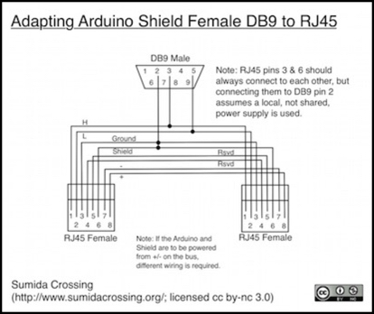
Note: Sparkfun recently changed their shield design. The v1.3 shield now supports two different pin assignments on the DB9, controlled by either jumpers or trace cuts (they say jumper, but the photos I’ve seen look like cuttable traces). This cable is for the original pin assignments (“OBD” on the new board). I can’t tell from the documentation if that’s still the default, but I think it is.
The requirement that the bus be continuous imposes a maximum length limit on the cable. The actual length depends on a very complex relationship of a number of factors, which are in turn based on physics I won't go into; it's basically about delay and signal attenuation. But this can be simplified into some basic rules:
- There is a minimum of 2 nodes and a maximum of ~30 nodes on the bus (see the LCC Node Limit section).
- The bus is at most 1,000' (300m) long.
- For each node added, subtract 20' (6m) from the maximum length.
- For each stub cable added, subtract 2' (60 cm) from the maximum length.
- There can be no more than one connection per foot (30 cm) of bus cable.
- There is a length limit on individual stubs and on total length of all stubs (see below).
- The bus, but not the stubs, must be terminated at each end with a 120 Ohm resistor.
The above limits are tightly related to the bus speed of 125 Kbps. If LCC ever allows faster bus speeds as an option, segments using those speeds will have different (and much shorter) maximum limits.
In addition to the CAN technical note, see also this PDF on physical limits of a CAN Bus (but note that it's describing a slightly different version than LCC uses).
Now lets look at these in a little more detail.
Connectors
LCC allows for two kinds of bus connection: screw-terminals and RJ45 connectors. The latter will generally be much easier to use. While I'm normally a big fan of screw terminals, in this instance I probably wouldn't buy a product that used screw terminals with an adapter cable for RJ45. It's just one more thing to go wrong, and extra complexity under the layout, where you really don't want unnecessary complexity. I want my LCC with RJ45 built in, thank you.
Although CANopen also allows for use of RJ45, it's not commonly used. Most versions of CAN hardware seem to use DB9 connectors (with two different kinds of pin assignment) or specialty connectors. If you're making your own cables, the plugs on the end (and the jacks they go into) need to match the Category 3 (or better) requirements. The most common connectors you'd find today are probably Cat5e, but those (and Cat6) are better than Cat3, so they can be used.
Note that "Voice Grade" wires and connectors are not suitable for Ethernet, and thus not for LCC, and should not be used.
Wire
As noted, CAN Bus wiring for LCC uses Ethernet cable ("unshielded twisted pair" of "category 3" or better, to be precise) with two or four pairs. Each pair is twisted around itself, which for high-frequency applications reduces emitted electromagnetic noise and prevents external noise from distorting the CAN Bus signal, or at least reduces the effects.
Note: Formally, "Category 3" requires four pairs (per the EIA/TIA standard mentioned earlier, which defines Category 3). That said, the category system is mostly about the wire used in each pair (gauge, insulation and the number of twists-per-foot) and so a cable with two pairs might informally be described as category 3 if it meets those requirements, even though it shouldn't be. More practically, an "Ethernet" cable without any category rating may be a two-pair cable, and that's really what LCC is stating as a minimum requirement.
At the LCC speed of 125 Kbps, a CAN Bus is limited to at most 500m of length (1,640 feet), but LCC limits the length to 300m (about 1,000 feet) to provide a timing/noise margin to allow for some other things, like long stubs, cheap electronics or poor wiring. However, the CAN in Automation (CiA) group recommends that segments at any speed be limited to 200m (656 feet), so that's probably a good upper bound on actual wire length in a single segment. This is a place where it's best to be conservative: pushing the limits may result in flaky behavior.
Within the cable, the first two pairs are the two wires of the actual bus, called CAN_H and CAN_L or just "H" and "L". Although which is which doesn't matter except to hardware designers; "H" stands for high and "L" for low, relating to the relative voltage of the two related to the reference ground.
Per the ISO standard, CAN Bus also requires a reference ground (formally called CAN_GND), and I'll cover that in more detail in the Grounding section. The second required pair contains two ground lines (CAN_GND and CAN_SHIELD) bonded together at each node to act as a single ground line.
The reason for two ground lines on an RJ45 is obscure. The CiA standard had two, even in its first edition of 1999, so that's not something the LCC creators thought up. It probably derives from the shield wire requirement in the ISO standard, but I haven't seen a copy of that to confirm that assumption.
I suspect that ultimately it's because the second pair had two wires, and they didn't have any good use for the second. Although it may be to give the ground line more capacity (in Amps) than a single wire would have. Whatever the reason, LCC says specifically that both are used together, and they have to be connected to each other at each node.
After the first two pairs, there are two more optional pairs, using up all eight wires in a category 3 or better Ethernet cable.
One optional pair is used for bus-powered devices. This is probably most useful for something like a hand-held throttle, but it could be used (with some limitations) for other things, like small nodes operating a signal mast. This pair can provide at most 500 mA of power within some sub-section of a bus, which is probably enough for 5-10 nodes at most. That's pretty limited, but it has to be due to the current-carrying limits of Ethernet wire (well, it’s a bit conservative but it allows for even the thinnest Ethernet wire, which is probably the right thing to do).
The second optional pair is reserved for future use, but the CAN technical note suggests that this could be used to carry a DCC signal according to RP-9.1.2. This is the NMRA "recommended practice" (kind of a not-quite-standard standard) that describes how to distribute DCC from a command station to boosters. If you're familiar with LocoNet, this is what the two RailSync pins are effectively carrying (I don't think they exactly conform to RP-9.1.2, but it's the same basic idea). If you have a large layout with boosters far from the command station, being able to use the LCC cable to get the DCC signal out to them will save some wiring, so it's a good idea.
Note: if you already have bulk cable for LocoNet or some other existing system, don't use it for LCC. It's not Category 3 (unless you bought something different from the usual) and won't have the correct performance characteristics to create a reliable bus.
LCC Node Limit
I mentioned a limit of nodes per bus of 30 up above, contradicting the CAN technical note. That deserves some explanation. At heart, it's a limit in the original ISO standard, which some transceivers were designed to use as a maximum. Some others don't, though, and apparently some specialized forms of CAN Bus allow more than 30 nodes. But without anything formal in the LCC standard itself, the ISO limit must be assumed to apply, and a manufacturer could choose to use a standard transceiver with a 30-node limit. Assuming you can put more nodes on a bus isn't a good idea, even if it might work much of the time.
While LCC doesn't formally state a limit for the number of nodes, it implies a limit of 45 - 47. If you had 48 nodes (the number suggested by the CAN technical note), the maximum cable length per the "rules" given there would be 1000-(48*20)=40 feet, and that's not enough to put each node one foot from the next, so the wiring rules implicitly limit you to 47. If every node were a stub, then the limit would be 45 nodes.
The text around those numbers aren't absolute rules though (and they're not in the standard itself); they're guidelines designed to keep you from doing things that would violate the underlying electrical limitations of the network. What that means is that more than 47 nodes violate the guidelines, and may violate the operational limits, but it isn’t a guarantee that 47 is going to work.
The limit of 30 nodes is on one bus, or more specifically a bus segment, not a whole layout. There are ways to break up a larger collection of nodes into multiple bus segments that we'll get to in the Bus Segments and Repeaters section. With repeaters, complex networks with hundreds of nodes should be possible.
Bottom line: going beyond 30 nodes without breaking the network up into multiple segments is asking for trouble. As with many wiring issues, it might work just fine for you. Or it might work fine, for now, and someday you'd discover your network being flaky with no clue as to why. Debugging those kinds of problems is intensely frustrating (I speak from long experience with other kinds of networks), so do yourself a favor and be conservative in wiring practices.
Stubs
Although a bus is one long wire, it's possible to have short side branches, called stubs. These are for a single node and most useful for things like a tethered hand-held throttle or adding in that one node you forgot to plan for.
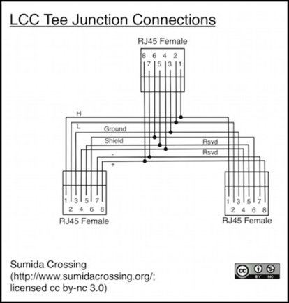
In truth, every connection to a CAN Bus is a stub, since the transceiver taps into the through wire between the two RJ45 connectors. That bit of wire from the transceiver to where it connects (typically only an inch or so (2-4 cm) is a stub. But what people usually mean by stub is a separate wire going off the main bus wire at a Tee junction (a place where three RJ45s wire together, instead of two).
The rule for stubs is that you treat the tee-junction like a node, and have at least 1' (30 cm) of cable on each side of it. You also have at least 1' of cable from the tee to the stub node (you can have more).
Electrically, the tee-junction is just the same as two RJ45s wired together. The third just has every pin connected to the two wires (e.g., all three "pin 1" wires join together, etc.). Two of the connections should be wired together and used for the main bus, with the third connector soldered to the others used for the stub (this has to do with minimizing reflections in the cable, and is another of those "you don't HAVE to do it this way, but it's a good idea" things).
The LCC standard itself is silent on the issue of stub connections except to note that they're allowed by the CAN Bus standard. The CAN Bus standard itself allows for short (1' or 30 cm) stubs in general, although some types allow longer stubs (e.g., there's an SAE standard allowing a twisted-pair bus with 1m stubs, but it limits the bus to 16 nodes). The CAN technical note implies that a small number of stubs longer than one foot will probably work, but doesn't provide any specific guidance.
There's actually a formula for calculating the maximum drop (stub) length and another for the number of drops in the CiA standard noted earlier. Fundamentally the limit is end-to-end delay across the bus, and the stubs add to this, but in a rather odd way. Thus the limit is based on things like bit-duration and propagation speed.
Here is the calculation for LCC:
For 125 Kbps, nominal bit time (T) is 8 usec. That's divided up into several portions, but the one that matters for us is the "propagation segment" or PROPSEG. For the MCP2515 transceiver (a common one) this is 500 ns duration @ 125 Kbps (one "time quantum" in some documents), which we'll call Tp below.
A typical worst-case propagation delay (d) for twisted-pair Ethernet cable is 5.7 ns/m. This is often rounded to 5 ns/m, which is probably a more typical number, but that may also reflect a different kind of wire, so I'll stick with the more conservative value.
The two formulas:
Ld = maximum per-drop length = Tp / 50 x d = 500 / 50 x 5.7 = 1.75m (about 69").
Lt = total drop length = Tp / 10 x d = 500 / 10 x 5.7 = 8.77m (29 feet)
So, if you use five-foot tethers, you can probably have 5 of them in use. If you limit them to three feet, you get nine. That's assuming you haven't used up more of the allowed delay budget in other things, like repeaters. I'd also read that as a theoretical best case, and plan to use fewer in practice. Note that that's a bus segment limit, and as we'll see below we can more than one segment using repeaters.
So, don't plan on having a lot of stubs on a single bus and don't make any of them too long.
Termination Resistors
The LCC standard just says you need to terminate the bus, but doesn't get into details (that's part of the CAN Bus standard). The CAN technical note has a fairly long section on bus termination, laying out three ways it can be done, and a couple of others you shouldn't use.
The important part here is that unlike DCC, where some people recommend adding termination resistors, but the standard doesn't call for them, and many networks work fine without them, the ISO CAN Bus standard does require them, and you really don't want to omit them.
Termination resistors on a bus essentially reduce electrical "noise" within the bus that can cause one node to not receive messages from another (and not necessarily the two most distant ones). This noise can cause very flaky behavior. While you might get away with omitting them from very short networks, it's a bad idea.
If you use a pair of 120 Ohm resistors (the simplest method, and probably the best if you need to make your own), those go on the two ends of the bus (and not on any stubs). That means past the last node, not between the node and the rest of the bus. Again, if you aren't pushing the limits of length, the lower-than-usual speed of CAN Bus may let you get away with omitting them or putting them somewhere other than at the ends, but it's another landmine you're planting for your future self as the layout grows. Pay attention to termination; you'll be glad you did.
Note that the standard doesn't say how heavy-duty the resistor needs to be. The LCC technical node says 1/4 Watt (250 mW) is fine. But also suggests that designers assume that a CAN bus could cary up to DCC voltage, likely as a safety measure against a simple miswiring blowing up every node on the bus.
DCC voltage can be up to 22 Volts,or 27V for DC, which is just over 6 Watts through a 120 Ohm resistor. Short that through a 1/4W terminator, and it won't last long. That's probably a good thing, better the resistor fail than the wire, which isn't going to handle 6 Amps very well either. But you do need to consider that the termination resistor may fail in "normal" use if you wire something up wrong.
Termination resistors may be available on an LCC node via a jumper. But with RJ45 plugs, a simpler method is just to make a plug with a resistor in it, and plug that into the open RJ45 at each end of the bus. Simple, easy to check visually when inspecting layout wiring, and if you fry the resistor, simple to replace.
I think the LCC standard should have mandated this approach in the interest of usability, and prohibited on-board termination jumpers, which are going to be hidden problems waiting to confuse people. But they didn’t, so you will likely have a choice of methods. I’m going to use visible external resistor plugs if and when I build a layout with an LCC network.
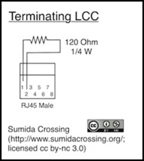
Note: if you make your own, 10% tolerance resistors are allowed, and as noted the recommended power rating is 1/4 Watt (250 mW).
Grounding
Grounding circuits correctly is important. But grounding in a bus has some differences from grounding in a simple circuit (or in house wiring, for that matter).
It's also a subject where I'm more likely to make mistakes. Note that I'm not an electrical engineer, just a hobbyist. The following is how I interpret the standards and other technical materials I've read, but it isn't guaranteed to be correct.
Now, consider a typical bus with four nodes, shown in the diagram below. The left-most node supplies power to the two optional +/- lines, and the third node uses this. The 2nd and 4th nodes have local power supplies. These nodes connect to the bus wires, with the CAN_GND and CAN_SHIELD connectors bonded at each node to provide a single "Ground" line. I've shown each wire as a separate line (omitting the two reserved ones) and shown the two ground lines connected together at each node (as is required per the CAN technical note).
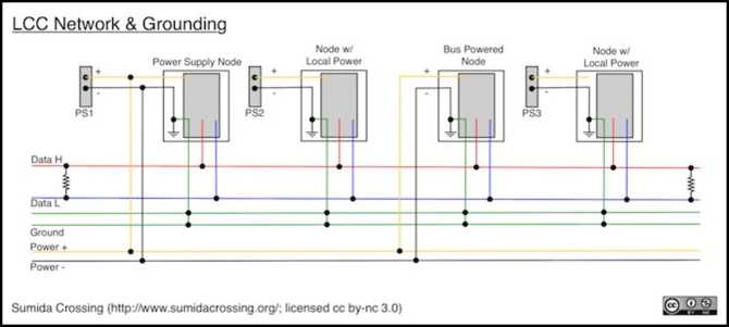
The three power supplies will typically be ungrounded "wall wart" types, with their negative output unrelated to any external grounds. Because all the negative lines connect to the ground on a node, and that connects to the ground line in the bus, the bus ground (green pair of lines in this diagram) ties the grounds together and provides a common reference for "zero volts".
But notice that two of the nodes also connect the negative line to the "Power -" wire, and that is used, in addition to the Ground line, by the bus-powered node. The reason, I presume, is that power use is going to be fairly "noisy", fluctuating as the node's processor takes various actions. Using "Ground" as the power supply common would expose the shield circuitry more directly to that noise.
There’s a comment in the CAN technical note about isolating the ground wire using a resistor/choke for noise filtering when connecting “Power -“ to the two ground lines, which seems to support that interpretation. I’m not sure of the function there, as it would seem to change the local value of ground, which might make actually interpreting the signals problematic, but maybe I don’t understand how they intended it.
But notice that this means that the third node actually has two separate paths back to the power supply for negative voltage: the Ground line and the "Power -" line. That's a ground loop, and ground loops are normally something to avoid. So why does LCC permit it?
The fact is that ground loops are bad because differences in delay and resistance between two paths can give rise to damaging voltage and currents on what should be a stable reference ground. Because both ground paths are in the bus wire, they're both going the same distance and using the same kind of wire. There's still some risk of differential voltage, but it's much smaller than if different gauges of wires taking different paths were used.
What the CAN technical note actually says is that it's up to the designer of a self-powered node if they want to use "Power -" or just let the Ground line be the return path. I don't think omitting the connection to "Power -" would be a good idea, but then I'm not a board designer. Maybe the minor savings in cost/complexity would be worth it for very inexpensive nodes. You’d still need at least a three-pair cable though (and formally per the standard you’d use ordinary Ethernet four-pair cable) so you’re not saving much by omitting the connection.
Think about another aspect: what if PS2 and PS3 weren't separate power supplies, but a shared "accessory" power supply. Then there would be a negative line between them external to the bus. This would be yet another ground path, and one of different characteristics. That's the kind of ground loop to avoid.
So, basic grounding tips:
- Always connect pins 3 & 6 at each node to each other and to the node's ground.
- If using bus power, additionally connect both "Power +" and "Power -" to the node’s power input and ground, respectively.
- If using a local power supply for a node, use a real "local" power supply, not one that will be used by other nodes (a few nodes in close proximity could probably share a supply with no issues, as the additional ground path would be short).
One question you might ask: why not isolate the H, L and Ground wiring from the +/- wires using opto-isolators or something similar? The answer is that some CAN Bus systems do exactly that. But you pay a penalty in additional signal delay, which makes maximum bus length shorter. And the transceivers required for it have additional circuitry, which makes them cost more. LCC does not mandate use of such isolation, which means that even if some nodes were isolated, others wouldn't be, and thus the system wouldn't be isolated.
So, we can't use an isolated bus to avoid problems because everyone isn't using an isolated bus.
Another thought you might have (I did) was, if CAN Bus is using a differential signal, why does it need a reference ground? After all, DCC uses a differential signal, and doesn't use one (think of a train: there are only two rails leading to the decoder, and no place to put a ground).
The reality is that CAN Bus isn't actually a true differential signal, it's two signals the inverse of each other. Transceivers reference each signal to ground (well, some do, some may use true differential processing). Part of this is because the CAN Bus standard allows it to keep working if one of the signal lines breaks, for added reliability, something you can't do with differential processing and no reference ground. And the fact that it was originally developed for use in cars, where the frame provides a reference ground (if you want it to) may also have something to do with it.
If you look around online, you'll find people reporting that short CAN Bus systems will work without a shared ground. You'll also find recommendations from people who seem to know what they're talking about that you really ought to use a shared reference ground. And keep in mind that the standard requires it. Wires don't get added to standards without a lot of thought and review, because a million cars with $5 of extra wire in each adds up.
You may see some advice online about not connecting CAN grounds at all. This assumes, I presume, either applications with short networks or that a common power supply is used, and thus every device has the same negative, and that's providing an identical reference ground on each node. That last is true in a car, but probably not on a model railroad layout. Frankly, I think it's bad advice even in a car: a wire in a bus is a more predictable ground than a car frame or power supply wiring; who knows what odd voltage transients show up there.
One last comment: notice that nowhere does the ground wire (or the “Power -“ wire) connect to any external ground. It’s not required, and it would probably be a bad idea to add such a connection, as it would provide an ingress for noise. The ground in CAN Bus is a signal reference ground, not a safety ground, and it doesn’t need to be “earthed” anywhere the way a safety ground does.
Bottom line: grounds are important: make sure you have them done the right way.
Network Structure
So, we're left with this: you can have up to 30 nodes on a CAN Bus segment. They have to be at least a foot apart, and if you have any stubs, their T-junctions need to have one foot on either side and a one-foot to five-foot cable to the stubbed node. You're also limited to 29 feet of stubs total, and thus no more than 29 stub nodes out of your count of thirty.
The maximum length of your bus will be limited by the number of nodes and stubs, and you should use the CAN technical note formula for that. But it's probably a good idea to keep the maximum length under 200m (656') no matter what.
Are 30 nodes enough for a layout? That depends on what you're doing. If all of them are 16-input/output boards, that's probably a pretty big layout. If each is a standalone device, like a signal mast or an occupancy detector, then you're going to run out fairly quickly and need to have more than one segment and link them together. That means using repeaters or bridges.
And if you want to connect with some other kind of network than a CAN Bus, and someday you will, that means using a gateway.
Bus Segments and Repeaters, and Bridges
The diagram at the top of the post shows a network with two CAN Bus segments (plus a wireless portion, but ignore that for now). The nice thing about repeaters and bridges is that they don't care about what's in the data, so existing ones developed for other applications should work for LCC. They do have to support the bit rate used by LCC, and not all will since it's optional. The bad part is that the existing ones are designed for high-reliability use in cars and automation control systems, and cost several hundred dollars each as a result.
A repeater's purpose is to connect two separate CAN Bus segments into one CAN network. Each segment is an independent electrical bus, and that means that all of the rules on length discussed up to now apply separately to each. Repeaters can also optionally provide "galvanic isolation", meaning that the signals and grounds on one segment are electrically isolated from those on the other. You can use more than one repeater to have even more segments.
Multiple segments allow you to have more nodes, or to have a longer maximum length, or both. They also allow you to "tee" off a separate segment. Consider a large layout with a couple of peninsula sections. If you run a single bus wire out and back along each peninsula it could get quite long. If you run the main bus wire around the walls and put repeaters at the base of each peninsula, with a separate wire running out to the end of each, you'll have shorter segments (but more of them).
Another application for repeaters would be tethered throttles. If your fascia panel is a repeater rather than a simple tee, then there's no limit on the number of them (well, there is, because each adds some delay, but it's a really big number). If I were designing a non-wireless walkaround throttle, I'd use repeaters in the fascia. The parts cost is relatively small, and you should be able to make an LCC repeater for under US$20 in total parts cost.
If you need more than two segments, it's often a good idea to treat one segment as a "backbone" and connect only repeaters (or bridges or gateways) to it, using each repeater to create one segment of up to 30 nodes. This helps with problem isolation, because a node causing a short will only affect one segment. If it's on the segment that connects all of the others, it would affect the whole layout.
It’s also better than stringing segments end-to-end with repeaters. If you do that, nodes on the two end segments have a cumulative delay from all of the repeaters in between. With the backbone approach, any two nodes have at most two repeaters worth of delay between them. There might be some circumstances where you’d want to connect two segments end-to-end (a really long backbone, for example) but that’s something that should be minimized.
Until someone makes an inexpensive LCC repeater, there are CAN repeaters on the market for a couple of hundred dollars (there are also some much more expensive). If you really need a repeater, a couple of hundred dollars is going to be a small part of what you're spending on LCC, but at current pricing they're not something most people would use otherwise. But let's assume you need one.
If you do, then you would need to select one that supports the 125 Kbps rate, and it's not going to extend anything other than the H & L Can Bus lines and perhaps the ground (i.e., not the power or reserved lines), so you might have to wire those up separately (or accept that they aren't connected).
Bridges probably won't be useful for the average modeler. Their benefit is that they support connections between different speed CAN Bus segments (so if LCC eventually adds 250 Kbps segments, you could have older gear on one segment with a bridge to a segment used for newer nodes). They also do some message isolation, so for a very busy network they can help increase capacity by keeping local messages local, but this depends a lot on how the network is being used (and a single CAN Bus has a lot of capacity for LCC use).
Gateways
Lastly we come to gateways. The LCC standard envisions the use of gateways to other kinds of networks in the future, but hasn't yet specified how these should work. The OpenLCB team is working on specs for a couple of them, apparently, but issues with their website links makes it impossible to tell if this is just a concept, or if either is well along towards standardization.
Gateways act by translating the protocol (that's the messages and session stuff discussed at the beginning of this post) from one physical network type (e.g., CAN Bus) to another (e.g., wireless). So even if someone made a gateway for use on a CAN Bus for some other application, it wouldn't know about LCC or be able to do the needed translation. We're going to have to wait for LCC standards, and for manufacturers to take advantage of them, before we have gateways to use. Until then, someone could create a proprietary one, but what's on the other side wouldn't really be LCC and might not, probably would not, eventually work with standard LCC equipment designed for the other network type.
Summary
So that's LCC via CAN Bus in a nutshell. Thirty nodes per segment, but segments can be hundreds of feet in length if needed. Termination and grounding are important details to watch when doing wiring, but the wiring itself is quite simple. Stubs for things like tethered throttles are allowed, but you need to keep them short and not have too many per segment, or use repeaters to have multiple segments. And you can use off-the-shelf repeaters if you need them, with a bit of caution.
Despite some of the areas where I think the standard is a bit soft (lack of a requirement for isolation, multiple ground paths, ambiguity on stub count and length) it is overall very well thought out. It looks like a good foundation for a control bus, and I'm hopeful for the long-term future as a result.
Next time we'll look at the messaging capability, what can be done with it today, and what promise it holds for the future.