


Investigating I2C
17 January 2016 23:21 Filed in: Electronics,Testing
Today’s post is going to be one of those interim ones I promised last time, where I report on progress made (or not), mostly about my work with testing the use of I2C as a short-range communications bus.
I decided to start with examining the code I’d written last spring, only to find that most of it was irrelevant as it was doing things the I2C hardware would do for me, or it had functional compromises I didn’t need to make now. About 90% of it got deleted, and I started working on something that would work with I2C, using a couple of my test programs to create a library that front-ends the internal Wire library used to directly control I2C. That’s working to the point that I can pass messages to/from the master, and detect damaged messages, but there’s a lot more to do.
In the Arduino, the I2C bus, which stands for Inter-Integrated Circuit bus, is known as the Two Wire Interface (or TWI). This is probably to avoid having to license the name from the original inventor, Phillips Semiconductor. The core patents have likely expired by now, allowing others, like Atmel, to do their own versions, but they can’t re-use the name. It’s the same thing under any name, basically, although Phillips (or rather their successor) likely has active patents on some of the newer capabilities. But the Arduino is fairly old-school in its approach to I2C, and that’s fine for my needs.
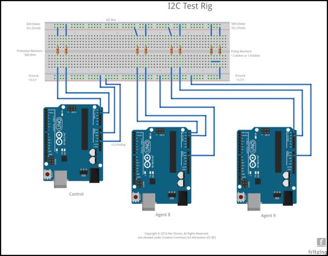
The above diagram shows the basic test rig I’m using right now. I’ll say more on that in a bit, but first a bit of background.
I2C
I2C is normally used for controlling or reading simple devices. It’s very popular in robotics, for example, because there are a lot of sensors that can communicate via I2C. Because of this, I2C has the concept that one device on the bus, called the master device, regulates all communications, and other devices don’t need to communicate with each other. Modern I2C has relaxed that some, as it now allows devices to take the master role when needed, although the Wire library doesn’t support this (or maybe it does; there are some undocumented changes in the code I need to look at some more).
But further, I don’t want to use the Master role for my devices, because in Wire, the master has to sit around and wait while a message is sent, which can take several milliseconds (I’m waffling a bit on this, see below). The other devices, called Slaves, get to use interrupts to send and receive messages, and can go off and do productive things while the hardware manages the bus communications in the background. I may look into fixing the master later with timer interrupts, but I suspect I won’t bother since I have another solution there (use a Raspberry Pi as master, as I mentioned last time).
Because of this central control and configure/report approach to communications, I2C normally works by sending out a “register number” (a one byte value from 0 to 255) followed either by data to write, or a request for data. But the hardware just treats the register number as more data. You can actually send an I2C message with no data, or with arbitrary data up to some limit. The limit imposed by Wire is 32 bytes, which is short compared to most networking systems, but my needs are actually going to be quite modest, so I’m limiting my system to a shorter maximum, for reasons I’ll get to.
My Use of I2C
The basic idea of my system is that there will be a Control Arduino taking the master role, but it won’t be doing anything other than communications. That alone will get quite complex, since that’s where any interface with a control bus will live, as well as some more complex human interfaces. Other nodes on the bus will be Agents, meaning nodes participating in my protocol, or ordinary I2C devices, which do not. This could, for example, allow me to have an Arduino communicate with an I2C device such as a two-line text display. I’d need to deal with a multi-master environment for that, so for now it’s a “nice idea” with no immediate plans for support, and I’m limiting my initial efforts to a simple bus containing only devices using my library.
Part of what I needed to deal with was data loss. The I2C bus is not a reliable transport method. The library and hardware can simply lose a message entirely if they’re busy, with no notice whatsoever. Messages can also be corrupted by electrical noise while in transit, and the usual method is to have some way to detect that, and discard on receipt (again with no notice to the software using the library providing the bus interface). So for reliable transport, basic messaging needs a way to sequence messages and detect when one hasn’t arrived, store the sent ones until confirmed, and resend as needed.
I began working on a simple buffering method to store the messages and the detection system. I expect loss to be a rare event, and storage is precious, so I’m using a simple circular buffer approach to the message store. This also decouples the act of transmitting/receiving from when the application creates or uses the data, which is something else I needed for application design flexibility. I have a basic version working, although it needs elaboration for the “resending” aspect (right now it’s a simple FIFO queue, and I need a bit more than that). I also selected, after some thought, the CCITT version of CRC8 as my loss-detection method.
CRC Testing and Selection
CRC8 is an 8-bit checksum that is fairly quick to calculate, although there are several CRC8 algorithms with slight differences. I chose the CCITT version of CRC8, which is not quite as quick as the Dallas CRC used by a lot of I2C hardware, but it may be somewhat more reliable (it’s hard to get good info on the robustness of different CRC algorithms, but they’re not all the same quality).
CRC8 is limited to providing the best protection to 14 bytes of data or less, which works well as I’m using a four-bit length (0 to 15) and I needed to reserve 15 anyway. This means that the most data in my messages will be 14 bytes (not counting the initial address byte or the CRC itself). I’m using three bytes for header information on simple “datagram” messages, and one more on reliable “session” messages, so I will be limited to 10 bytes of reliable information, or 11 for “unreliable” datagram messages. This is more than I actually expect to need.
CRC8-CCITT can be calculated in two different ways, as a bit-shift iterative algorithm, with lots of instructions (time) per byte of data, or as a table lookup algorithm, where each byte or half-byte (called a nybble by computer scientists) is looked up in a list of pre-computed values (which take up space). Which version to use is a classic time/space decision: fast tables using SRAM or slower iterative algorithm using little memory. This is complicated by the nybble tables being something of a compromise between the two.
I used an online tool, pycrc, to generate multiple forms of CRC8-CCITT and CRC5, as well as testing some other algorithms I found while searching online. I also tried the Polulu CRC7 algorithm and a CRC5 algorithm assuming these would be faster than CRC8, if not as good. Here’s a summary of timings. All times are in microseconds to compute the CRC over 10 data bytes (that would be header plus 6-7 data bytes for me).
- CRC8-CCITT: full table: 12 usec, nybble table: 76 usec, bit-by-bit: 108 usec
- Dallas CRC8: bit-by-bit (version 1): 92 usec; (version 2): 80 usec
- CRC5: full table: 88 usec, bit-by-bit: 116 usec
- Polulu CRC7: 40 usec
Note that a CRC7 algorithm, while fast, will miss a lot of errors that a CRC8 will catch. Surprisingly the less-accurate CRC5 wasn’t even as fast as the better CRC8 algorithms. The Dallas algorithms were fairly quick, for bit-by-bit algorithms. The one marked version 1 appears to be the original, while the one I’ve called version 2 is an optimized form from this website, which produces the same CRC value.
I decided to use the CCITT version as 18 additional microseconds aren’t a huge problem if I use the bit-by-bit version, and with table lookup, the speed is only dependent on the number of bytes, since the table is pre-computed. I haven’t decided if the extra 240 bytes of memory neded for the full-table version are worth the savings over the nybble look-up speed, those 64 microseconds saved might matter, but it’s rather doubtful. I will use at least the nybble-table version, as it doesn’t use much memory and the speed gain is significant (although its about the same speed as the Dallas algorithm that is bit-shifted).
There’s a lot that has to be done to send or process a received message, typically taking hundreds of microseconds. At the standard bus speed, that still leaves plenty of time; a 10 byte message takes several milliseconds to send, so even back to back there’s a lot of time between them. Still, things like pin writing can take hundreds of microseconds. I may need to shave tens of microseconds before I’m done. For now I have both algorithms in as compile-time options, and I expect that even after I pick one as my default, I’ll leave the other in as an option for users of the library.
Testing
And now for the test rig. As shown, I have two Agent nodes, plus a Control node. Most of my tests only need one of the agents, and I have it and the control hooked up to separate computers running the Arduino development environment so I can run serial monitors on both for the Arduinos to print out status messages. When I need the third, I program it and hook it up to an external power supply (with its ground tied to the common ground).
Although I ultimately want to use Pro Mini 5V Arduinos (my local store has clone versions of these for US$6 each this week), I’m testing with the Uno as its functionally equivalent and easier to work with (the I2C connecters are oddly placed on the Pro Mini and not breadboard-friendly).
Each node is connected with three wires, SCL, SDA and ground. The ground is close to a star type, with one edge of the breadboard used for it. The Control node is also being used to supply 3.3V to the pull-up resistors. I’ve disabled the Arduino’s built-in 5V I2C pullups by the simple expedient of calling PinMode after Wire.begin, to put each pin in INPUT mode. The built-in pullups are the wrong size for I2C (although they’ll work fine on short distances) and I wanted to run my bus at 3.3V rather than 5V to see how well that works.
The naming of my two agents in the diagram comes from the addresses: 8 is the first legal address on an I2C bus (the bus master doesn’t need an address, and is implicitly address 0). I actually numbered my nodes 86 and 99, just to space them well apart for testing things that need to poll through the full list. If you can guess why I selected those two numbers, you’re probably even older than me.
I’m using 1.8 kOhm pull-up resistors, as these are optimal for 3.3V I2C. Well, 1.5V might be better, but they’re close to optimal, and the Raspberry Pi uses 1.8V so I’m also trying to see how a Pi-driven bus would work without a level-shifter. I want to see if I can skip the level-shifting circuitry and still get reliable operation on a bus with mixed-voltage nodes (5V Arduino and 3.3V Pi). So far, it seems rock solid, although I haven’t tested this configuration with my Pi yet.
Another reason to use 3.3V even with just Arduinos is that it comes off a different regulator on the Arduino board, so it will be more stable than if I’d used the same 5V going through the Arduino circuits. I may end up using a separate supply in the final system, but that’s still TBD, and right now the 3.3V looks very clean.
It’s important to note that the grounds all have to be tied together. This provides a reference level, otherwise a “1” voltage on one node might not look like a “1” to another node. The positive voltages, on the other hand, should not be connected, although having other nodes see the 3.3 volts from the Control node on the bus is okay since that’s not a direct connection between power supplies (it goes through the pull-up resistors and into the pin-sensing electronics).
Note: in all likelihood, connecting the positive voltages together would work fine. Model railroads do that sort of thing in DC block systems all the time, but then DC block systems tend to be quite robust as power systems go, and small switching power supplies, voltage regulators, and USB interface hardware is much more delicate. And unlike railroad block power for trains, it’s not necessary here. I wouldn’t take that chance.
I’ve also tested both with and without the 300 Ohm protection resistors, and they have a negligible affect on signal shape (as expected). Those resistors are important to protect the Arduino pins from potential voltage surges that could be induced by electrical noise (e.g., from a nearby DCC track bus). I eventually need to do some testing next to track with trains running, but that comes later.
I also tested replacing the link between Control and Agent 8 with one meter of dual twisted-pair wires to see how well that worked. Dual twisted-pair, with each line twisted around a ground, has the best capacitance of anything other than three-wire ribbon cable, and ribbon cable is a pain to work with so I’d rather not for the marginal benefit it brings. Twisted-pair cable is easy to get; I simply took apart a length of Ethernet cable off the 500’ spool I keep for projects and home wiring.
Again, note that the ground is a star ground to avoid ground loops. That means that both twisted-pair wires actually have the ground side connected only at one end. This will be a bit more complicated with a long multi-node bus (the whole length needs one ground point), but that should be easy enough in practice.
Even with a meter of wire, the signal was nearly pristine; much better than I’d expected, really. Here’s a trace from my Saleae logic probe. The thin blue lines are analog, with the lower one corresponding to the clock pulse (SCL) shown by the orange line. The white line at the top is SDA. The faint dashed white lines show the ground and maximum signal levels (a bit under 3.3V).
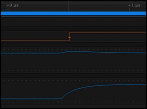
SDA/SCL trace: digital at 100M samples/sec, analog at 50M s/s
The signal begins rising just before the +0 ns line where the clock goes high, and is mostly at full within half a microsecond or so. That’s controlled by the capacitance in the wire (longer wires means more capacitance to be charged to bring the signal up, and so a longer rise time). It’s also affected by the pull-up resistor size (smaller resistors mean faster charging and a quicker rise time, which is why the Arduino’s built-in 20K+ resistors are bad).
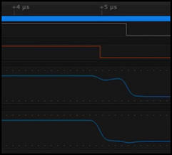
The fall time is basically controlled by the I2C hardware in the Arduino. It has some built-in resistance used when it pulls the wire low. As you can see here, fall time is much more abrupt, so it’s not going to be the limiting factor on length.
The analog signals also show some interaction between the two signals (SCL and SDA). This is because both are drawing on the same internal power supply, and there’s a limited number of electrons to go around. It doesn’t have any effect (nor should it with well-designed hardware), but it’s part of the reason that SDA is only considered valid in the middle of an SCL pulse; at the edges, odd stuff happens.
I wasn’t testing in the noisiest of environments, although the test rig was just 10 cm from my laptop and within a meter of several computers and LCD monitors and there was a wi-fi hub a couple of meters away. I saw a little longer rise time for signals (due to having more capacitance in the wire to charge) than with no wire, but as long as it rises in under about 4 microseconds it’s going to work fine. I’m guessing that in a noise-free environment I might get close to 8m of bus length with this design (grounded twisted-pair and appropriate pull-ups on 3.3V). I’ll have to see what 4m or 8m of wire looks like at some point, although I don’t expect to use that long a bus in real-world applications.
Still, this says that I have a huge safety margin on length at 100 kHz if I’m careful about wiring. That’s really all I was looking for at this stage in my testing.
It also suggests that I can probably get short (2m?) bus wires to work reliably even at 400 kHz, which would reduce the time the master node has to wait while transmitting. That might be useful if I do multi-master later, although I don’t really need it for my current approach.
Display Test
One of my tests this weekend was to try using a simple two-line display on the agent that wasn’t hooked up to a computer, so I could write test messages to it and see that it was working even without a serial monitor. Although this is helpful for testing, I’m also considering this longer term as something I’d drive with one of the Arduinos for uses like a simple speedometer mounted on the layout fascia (two IR LED/photodetector sensors at a known spacing will let me calculate scale speed of passing trains).
For my first test, I used a parallel-interface two-line LED display. These are common, and sold by a number of companies in parallel, serial, and SPI/IC2 variants. I used a parallel version (which only needs six pins), the Sparkfun LCD-00256, mostly because that was what was on the shelf in my local electronics store. But I also like the parallel approach as it avoids some of the complexity around serial.
This was remarkably easy to get to work, and power use is low enough to be provided from the Arduino’s supply. I did have to solder on a set of header pins so I could plug it into a breadboard (I’d use wires for one installed on the layout). The only thing I forgot to buy was a 10 kOhm trim pot for the backlight, but grounding that pin produced a readable display, and I’ll add a pot later.
Initial tests show that it takes about 320 microseconds to send one character, and just under 750 microseconds to send a number that displays as two digits (there’s some conversion time on top of the character transmission). That means a short message can take several milliseconds, although in a speedometer application I can probably live with that. Apparently if you use four more pins it will run faster, and that’s on my list of things to test (I also want to get and test an SPI version).
Clearing the display takes a surprisingly long time, over 2.3 milliseconds, which has to be added to the write time, although I’ll look into ways to avoid/minimize that (scrolling text may work, depending on how long that takes).
Lessons Learned
I’ve had a good couple of weeks playing with this now, as I write code and test it over and over, and I’ve learned a few useful things, some of which are fairly well-know if you search online, although a couple had me chasing myself in circles for an entire evening before I figured out what was going on.
First: since I2C works by the nodes “pulling down” the SDA signal voltage or SCL clock voltage, anything that interferes with that will prevent the bus from working because it looks like another node has pulled the bus low to pause activity (this is called clock-stretching). The usual symptom in that case is that the master hangs when it attempt to use the bus, waiting for some other node to release the bus. I discovered that an unpowered Arduino (my agent 9) would pull the bus low, but only after losing 4 hours trying to figure out what I’d broken in the software. Now I unplug SCL and SDA from agent 9 when it is not in use.
Second, the Atmel TWI hardware in the Arduino will return bytes full of 255 if Control asks for more data than an Agent sends. In general that doesn’t cause me a problem, because one of the bytes I send contains a length, so I can ignore extra data. And it’s a local problem: the extra bytes aren’t sent over the wires, so they don’t add any time. I did discover that this also happens if the agent rejects the communication and returns nothing (by never calling Wire.Write in the OnRequest interrupt handler). Since 255 in my header looks like data, I needed to reserve a length with all bits set (15) as an illegal length so I could discard those (actually, I could probably just depend on the CRC rejecting them, but I don’t know that some series might general 255 as a valid CRC, so I’m not going to take chances).
Third I discovered that you can’t really set up an interrupt handler from inside a C structure (not without some simply ludicrous gyrations). Then I discovered that Wire’s “interrupt handler” isn’t a normal one and it’s actually fairly easy to do for its needs, as long as you only have one instance of the structure (and with only one bus, I do). I could actually solve the larger problem with some kind of dispatch table, I expect, but I don’t need to do that for what I’m doing.
One last thing is that the Wire documentation is really wrong in places. I’ve taken to keeping the actual library open in my text editor and just consulting the code, but even that isn’t always clear. One particular problem is that requestFrom does not return the count of bytes read as it claims, but merely a copy of the number you requested (because it doesn’t know, because the hardware returns the number you asked for with 255 padding). This is actually well-known, but of course I didn’t know it until after it tripped me up.
Next Steps
I have a bit more code to write before I can pass even unreliable messages between Agent 8 and Agent 9 through the Control acting as a switchboard. Once I get that working, I need to start thinking about adding reliable messaging, although I may go and work on one of the other bits first, or start working on my CTC software.
I also have a couple of other projects I want to work on that are part of this larger project. I may go back to working on the Raspberry Pi for a while, but I also just received some RFID circuitry, and want to experiment with that for detecting trains as an alternative to DCC-based train identification, which requires adding circuit boards to each locomotive. RFID just requires gluing a 2mm cylinder somewhere on or in the locomotive, and the cost per train is a modest US$5 or less (although the detectors are around US$35 once I add all the bits, not counting the Arduino).
And I might not need to implement this myself. After a bit of googling, it turns out that someone sells Arduino-based systems to do RFID for model railroading using the same hardware I am considering. They’re using Ethernet as the communications method though. That’s simple, but an added cost for each reader I’d like to avoid. I have no experience using their product, although apparently this is the system that was described in a recent issue of Model Railroader so I’d presume it’s fairly solid.
And at some point I need to build a small interlocking testbed I can run trains through, with a bunch of sensors, signals and turnout motors, with Arduinos. I’m a ways yet from needing that for testing, but it might make for an interesting diversion from sitting at the keyboard.
There’s more than enough to do for my limited hobby time, and enough different things to keep my interest level high. This is looking to be a good project.