


Car Lighting Power Protection and September 2010 Status
There isn’t much status to give for this month, as the only major layout event was finally completing the Rapid/Shinkansen loop and running DCC trains (a major milestone, but one I’ve already covered). But this month also marks the one-year anniversary of when I first started keeping this record (I didn’t actually get it online until November, but I was making offline entries and writing down design information from September 2009), and it’s worth a short look back on the year.
Last September, I’d finished assembling and painting the baseboard “tables”, but not yet attached foam to them. I spent a number of months (into January) doing various tests to determine how I was going to build the terrain to allow a subway loop to exist, what proportions of height looked right for bridges and other structures, and various non-operational things (like the right kind of lights to use). Real construction started in February with the “River Crossing” scene. The “Urban Station” scene followed, although it’s really just track even now; there’s less there than on the relatively undetailed River Crossing scene. And the summer largely went to electrical work, and gradually getting the layout operational.
And, although it’s not yet fully operational (I need to finish gluing down foam and roadbed on the “Riverside Station” scene to complete the commuter loop), I can now run trains on four of the six tracks, including DC on the two Rapid/Shinkansen tracks, and DCC on any of them. While it’s been a long time coming, it’s now at the point where I can have fun playing with trains, and not just planning and building the layout (although I do enjoy that aspect also). All in all, a good year’s work.
The other thing I’ve been doing for most of September is working on a way to deal with flickering interior lighting on my commuter cars. I’d mentioned last time that I had some ideas about preventing this, but it wasn’t until this weekend that the prototype was built and tested. Although I haven’t yet installed this in a car, it’s to the point where the prototype works, and I think it’s going to do the job, so I’ve written it up. There’s a very long explanation in the Electrical section, with background, information about testing, and circuit diagrams and parts lists. I’ll just summarize the high points and talk a bit about the “why” of the problem, an aspect I really didn’t cover on those pages. I’ll post again after I get some finished units installed in cars and run, but that may be several weeks away, as I have other things to work on first.
Caveat: before going any further, I should note that my designs are using 25 volt capacitors. There’s a risk here, as while typical N and HO-scale DCC systems use no more than 14 volts, some beginner’s systems are known to use higher voltages (some even exceed the limit of 22 volts in the standard). And capacitors fail badly when their voltage is exceeded, often with destructive results to whatever surrounds them. The usual practice is to select a capacitor rated for 1.5 to 2.0 times the largest expected voltage. To be safe on all DCC systems, a 35 volt or 50 volt capacitor would be needed. But capacitors get much larger as voltage increases, and I’m optimizing for N-Scale. If you use these designs for other applications, or if you want to be able to run your cars on someone else’s system, keep this caution in mind, and either test the DCC system first with a prototype or check its voltage with an RRampMeter, or use a larger capacitor.
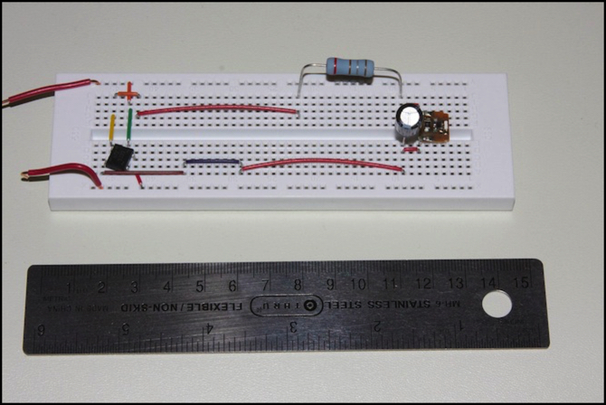
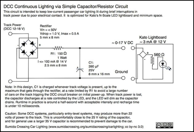
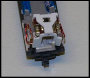
The circuit is a simple one: a rectifier (black square on left in above photo) converts track power to DC, a resistor (big gray blob top right) provides inrush current limiting, and a capacitor (round object center right) stores about half to 3/4 of a second of power for the lightboard (rectangle at right). This circuit is optimized to work for the very low power draw of Kato’s 11-209 LED lighting (which is about 3 mA, far below typical LEDs). When the lights lose power, the capacitor drains through the LED, which starts out bright and gradually dims. It actually stays lit for tens of seconds, but for most of that time it’s so dim you won’t be able to tell when it’s inside a car body. But the bright light lasts much longer than I’d thought it was going to, and that’s a welcome surprise. And I think I’ve made the circuit small enough that it can be hidden in the ends of the commuter car, where it won’t be too obvious.
The components in the photo aren’t the exact ones I’ll use in the final diagram. The capacitor is, but I’m going to use a surface-mount regulator that’s a bit smaller than the four-pin IC-package one used in the prototype, and I’m going to replace the bulky 2W resistor with a 1W model, as my testing of the smaller one did not turn up any problems with resistor heating, even after dozens of back-to-back charge/drain cycles.
The problem with Kato’s lighting flickering appears to be due to a design flaw in the car structure. The metal wheels pick up power and transfer it to wipers on the trucks, these feed up (from both trucks) via tabs to a pair of brass strips that run the length of the car, so all four wheels on each side are picking up power. These strips appear to be free to loosely flex as the tabs from the trucks move up and down in response to track irregularities or the body tilting on curves. This should prevent dirt spots or rough track from causing outages. The lightboard connects to these strips indirectly: it has two prongs that bump up against a pair of “L”-shaped brass strips, and those in turn slide into the car floor between two layers of plastic, bumping up against the lengthwise strips. That appears to be the weak point, although it could also be the connection from the trucks to the strips (but again, both trucks being live should solve that kind of problem).
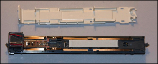
Top-down view of cab car with floor removed, showing lengthwise brass strips (and space for decoder)
To test that it wasn’t just poor placement of the lightboard itself, I actually soldered the lightboard to the “L” strips on one car (actually I soldered a short length of wire between them, to enable the board to be maneuvered into the bracket that holds it in the car). I did this on a car of the E231 I detailed last week that had serious problems with flickering, and after this change it continued to have the same problems. Doing this wasn’t easy (I used 24 AWG magnet wire, and it proved hard to bend into shape; I should have used either stranded wire or thinner magnet wire). In the process of installing the lightboard, I broke part of the bracket that holds it in place. Fortunately this doesn’t appear to hurt the alignment since the car body keeps it from moving once it’s assembled.
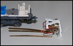
Lightboard with connected strips

The lightboard itself
In working up the circuit design, I’d first come up with a more complicated circuit using a voltage regulator, the idea being that this would provide constant-intensity lighting. It didn’t, for reasons that still aren’t clear to me, but more importantly the need to power the regulator at a fairly high voltage drastically shortened the runtime, and with capacitor size limited by a desire not to obstruct too much of the car’s interior, that was a problem. It was also a slightly more complex circuit, and I’m going to eventually need to assemble a lot of these, so extra components mean extra work (the cost is negligible, it’s the hours of soldering that are a problem).
After thinking out the initial design, and even buying the parts, I did some research (yeah, cart preceding horse yet again) and turned up a number of similar circuits, but I also turned up a commercial product (see references on the “long explanation” page) that used a rectifier/capacitor combo to maintain power to LEDs in a similar manner. I thought about just buying those, but I wanted to maximize capacitor size and place it away from the electronics to make it less obtrusive, and I wasn’t happy with the apparent lack of any inrush current limiting, which led me to the simplified (compared to my original) design. I could still use them, and just add a resistor, if I really wanted to.
After a couple of re-thinks, I was satisfied enough with the revised “simple capacitor” design to order the real parts to assemble that design for my first train (even though I hadn’t prototyped it yet). Prototyping followed their arrival (I didn’t have the right size resistor or capacitor from my original shopping trip, and I wanted to test those). The prototype worked better than expected, so I’ll eventually start assembling and installing these, likely as part of detailing my second DCC train. Although I might test the design out on a couple of cars of the existing train that are having serious lighting problems.
The reason I’m concerned about inrush current limiting is that capacitors act as a dead short when they initially charge up after power is first applied, and I’m looking to have 10 to 15 fairly large ones on one section of track, powered by DCC with fairly sensitive circuit breakers. It’s possible that the rush would be short enough (its over in milliseconds, and very few of them) not to trip the breaker, but even if that’s the case, it’s putting a high load on both the rectifier and the capacitor, which will shorten their operational life. And if it did trip the breaker, the system would never power up, because the LED would burn off any stored power before it resets, and the cycle would just repeat. There were some sound decoders that experienced exactly this problem, and I likely will have a lot more capacitance on a ten-car train than in one sound decoder. An eight-cent resistor seems like cheap insurance, even if it does mean more work for me.
So I think I understand the problem, and I have a circuit design, and I’ve tested that it works. I’ve actually been working on this for most of September, so it’s good to bring it to a temporary stopping point. I think I’m going to get back to work on the Commuter Station of the Riverside Station scene (I really want to run trains on all four tracks around the big curve). Getting that operational will probably be October’s big project.
Other website changes:
- Updated the Reservations page.
- Added diagrams to the Diagrams photo album, and photos to the Electronics photo album for the work I’ve done on the lighting protection pages.
== Comments copied from old system:
Monday, October 4, 2010 - 07:08 PM
Don
Very interesting. A few quick notes (we can converse in more depth over email):
1) Consider tantalum caps. They are smaller than aluminum electrolytic for the same capacity. Also more expensive, but the space savings may be worth it. Also, they are not polarized, which may help when you're assembling the 20th unit for the evening and are starting to mentally fade a bit…
2) Don't both with a voltage regulator. Your problem is not irregular voltage, but total voltage loss. Regulators take an input voltage, compare it against a reference voltage, and adjust their output up or down accordingly, such that the output remains constant. However, when the input voltage < cutout voltage (typically 2V for LM317), the output voltage decreases as a linear function of input voltage such that when in = 0, out also = 0: Precisely the situation you are trying to remedy! So stick with the single caps, and there's not need for anything fancier. The regulator circuits are mostly aimed at maintaining a constant (more or less) voltage to a lamp on a pure DC layout where the input voltage can vary quite a lot, and aren't addressed to your problem at all.
3) Remember that adding a rectifier decreases the voltage available to the LEDs. FWIW. Which isn't much.
4) Useful info: The time-constant (time for cap to charge or discharge about 2/3's of its stored energy) of an RC circuit (resistor-capacitor circuit) = resistance in ohms * capacitance in farads. This should help you figure out the proper size cap without a whole lot of experimentation, once you know the minimum voltage that will light the LEDs sufficiently bright for your purposes. Suppose that 8V is enough, and you are feeding the cap 12V; then you can use the time constant as a good first approximation of the effective time that the circuit can go without power and remain sufficiently lit. (adjust of 8V is too little or too much).
5) Notice that there are /two/ time-constants in play, because of the two resistors: One for charging (through the resistor you inserted), and one for discharging (through the one on the circuit board). Notice too that the combination of both resistors will further limit current into the LED, so the total current going to hte LED will be less than you think under normal circumstances.
Anyway, this is really good stuff! I look forward to seeing more!
Tuesday, October 5, 2010 - 04:12 AM
KenS
1) Tantalum caps of the necessary capacity and voltage run around $30, which is a bit much per car.
2) Ah, that explains the behavior. I'd assumed it shut off below the minimum input voltage.
3) Yeah, that's one reason I went for the SMD model (which had a 1.0 volt drop, rather than the 1.2 of the IC model I used to prototype it).
4) I hadn't turned up that formula. I'd need some way to figure out the minimum voltage for the LED, and I don't have a variable voltage source. But more importantly, I don't think it describes the discharge time for if the LED, as the 560 ohm resistor and 390 uF capacitor implies a 218 msec discharge, and I seem to be getting about three times that. But perhaps that just means the LED stays bright to well under 1/3 voltage.
5) Good point.
Saturday, October 9, 2010 - 11:57 AM
Don
$30? Naw. I bet you can get the cap size down a bit from 370uF, which is well within the shock-yourself-across-the-room territory. A 25V 68uF tantalum cap shouldn't cost you more than a couple of dollars, and would be about the biggest you might need, I would think…but perhaps I'm mistaken on this point.
