


Wiring Without Solder
11 July 2011 22:21 Filed in: Structures,Electrical
Well, I’m not moving the site just yet. Conversion of pages is going more slowly than expected, and there are more pages that I consider necessary than I first thought there would be. So I’ll probably have a few more posts over the next couple of weeks before switching over to the new software and hosting provider. However, for the curious I’ve included some jpegs of the new main page and one of the subordinate pages showing the new layout and navigation links in the Diagrams album (these are reduced somewhat by iWeb; the type used for text on the page is about the same or slightly larger than the type used today).
Today I’m going to talk about how I’m doing wiring without solder (well, mostly) for my structures, using the expressway as my case in point since it’s the first structure being wired. This is a technique I’ve learned from others, although I think I’ve brought a couple of bits of my own to it. And it’s one I plan to make substantial use of. There’s a page describing this with links to vendors of supplies, so I won’t get into that here.
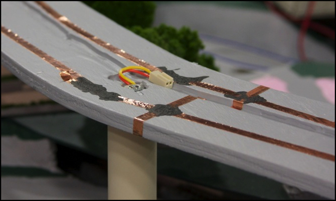
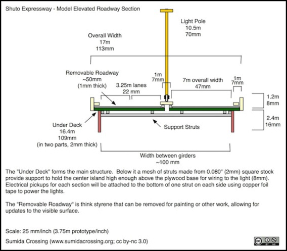
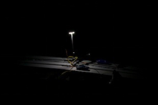
The Expressway is a four foot long structure that will eventually include a roadway assembly (road, guardrails, signs and streetlights) made of styrene, which rests atop a narrow winding strip of plywood held up by 1/4-inch threaded rod sheathed in one inch PVC tubing (the photo above shows the plywood, tubing, and the nut on the top of one of the rods). The Expressway page has more detail about the design, and the Tōkyō Metropolitan Expressway page has photos of the prototype I’m modeling. The Tōkyō Highway Scenery page has additional photos of the expressway system.
Expressway Deck
The roadway deck of the expressway is essentially a plastic structure, with lighting, that needs to be easily removable from the layout to facilitate moves. This is similar to the way my plastic buildings will rest in/on the street/sidewalk assembly that’s glued to the table-top. So I’m using this as a proof-of-concept of my plans for the future building wiring. The deck is also the project I’m doing for the JNS Forum’s Summer 2011 contest, and is described in a thread there, as well as a page on this site.
The deck is actually going to be built as a set of structures that link together and rest atop the plywood strip due to gravity alone. The idea of using copper foil tape as the contact between the removable structure and the fixed table is on that I learned from Inobu (see this post on the JNS Forum).
The copper tape doesn’t adhere very well on its own, although sandwiched between a building and the table-top it should work just fine. I’ve had the ends peel up from the painted wood after just a couple of days, and I’m considering gluing them down with something. Also, the test strip I made a month ago with copper tape on a sheet of styrene peeled up at one end.
So the other thing I did was to make use of Wire Glue to reinforce where strips of the tape crossed each other (I laid the tape in short stretches of 8-10 inches, so there were several such points). Wire Glue is a water-based glue that contains some conductive material (I suspect its a form of graphite due to the black color). It’s very liquid and tends to run, and needs to be applied fairly thickly and on a very level surface. But once dried it forms a fairly strong bond. I wouldn’t use it some place with a lot of mechanical stress (like in a DCC decoder install), but otherwise it should hold up over time. Some judicious reinforcement (e.g., by applying super-glue over it) can help, although don’t do that near any clear styrene (like in a building with windows) or the super-glue will fog it.
And the combination of foil tape with wires connected to it using Wire Glue has a very low resistance and a good current-carrying capability (ampacity). I tested a 10-inch (25cm) strip of the narrow (1/8” or 3mm) foil tape. This had resistance too low to measure (0.1 Ohm or less). When tested with up to a 1.2 Amp current from a 12V DC supply, I found no appreciable heating after five minutes. Even the multiple glued tape joints on my expressway only show 0.5 ohms end-to-end (which is likely mostly in the glue between the foil strips).
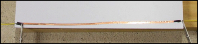
Foil Tape Test Strip (the aluminum clamps were used to hold the wire on while the glue dried)
So the idea is that the lights on each deck segment will have their wires connected to foil tape on the underside of the deck using wire glue, and those foil strips will rest atop the foil strips run along the plywood to provide the electrical contact. My only concern is that the deck may be too lightweight to make good contact, but I can add weight using the self-adhesive lead weights used in model railroad cars if I need to.
Now I said this was “almost” without solder. There’s a plug/socket arrangement (you can see the socket in the photo at the top) that connects the power wires running up through the pillar to the copper tape laid atop the plywood. This is going to be disconnected any time I remove the plywood, which I may do to work on it on the workbench, or for access to the scenery below it. I’d originally planned to glue the plug to the foil, but given the repeated use it’s likely to get, and the fact that it’s on plywood where heat isn’t a factor, I ended up soldering the plug’s wires to the foil tape (which worked fine). But glue would have been fine if I wasn’t going to disconnect it often (or was willing to re-glue it if problems developed).
I made an initial test of the roadway power bus and one of the 12V DC LED lamps I’m planning to use to see how it worked. In this case a clamp was used to press the wire agains the foil, rather than gravity and the weight of the roadway, but that detail aside it worked as expected. See the Construction photo album for larger versions of these photos, and the Diagrams album for larger versions of the expressway deck design. See my JNSForum 2011 Contest page for more about the electrical design of the expressway and the LED lights I’m using.
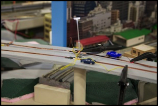
Foil/Lamp test
So while I’m not done yet, early indications are that this “solderless” approach to structure wiring is going to work out. And that’s good. I don’t mind soldering when it’s necessary, but the idea of doing it around expensive plastic structures doesn’t appeal, and assembling all the lighting separately and then gluing it into the buildings just seems overly complicated to me.
Other website changes:
- I’ve added a note to the DE10 page about the gold detail part, which turns out to be a “whistle” (aka Horn) per a Japanese railfan who contacted me about the page. I’ve also added some more material there about alternatives for DCC decoders, other than the Digitrax model I used for my DE10 installs.
- I’ve added a brief note to the “Phase 2l” Construction page about the work on the expressway.
- I’ve added information about TOKI gondola cars (which I’d omitted as the pages aren’t easily found on Japanese Wikipedia) to the Prototype Freight Cars page, and a photo of one of them in MOW service to the page describing the Etchujima Cargo Line used by JR East to serve a ship terminal for welded rail.
- I’m still working on the Tomix signals I mentioned previously, and have added more notes to the DC Signals page regarding them. I’ll have a full write-up in the next week or two.
