


Wire
I went off on a tangent this past week. It all started when I asked myself: what gauge wire should I use on my decoders? And the root of that question was thinking that the wire I’d used on my first install, two weeks ago, was too thick. The answer turned out to be less obvious than I thought it would be, and consumed (and is still consuming; I’m not done) a lot of time.
Googling about didn’t turn up much in the way of recommendations. Digitrax sells 30 gauge (30 AWG, roughly 0.25mm diameter or 0.05mm2 for the metric folks in the audience) wire, so that’s a fairly solid recommendation. But then at a model railroad show I turned up a display of wire from ESU (part 51940) in 36 ga (likely really 0.125mm metric wire, not 0.1524mm 36ga). And I’ve seen reference to some pre-wired decoders using 28 AWG rather than 30 AWG (probably HO decoders).
Okay, so obviously I just need to look up my power requirements on an ampacity table, and I’ll know the answer. I know most of the N-scale motors I’m working with have a stall current around 240 mA, and sizing for stall current makes sense, as it is the highest current that could be drawn, and it could be drawn for an extended period of time if the train got stuck against an obstacle. If my decoder did both lights and motor I’d need to add to that, but my EMU decoders are motor only. So, what gauge do I need for 240 mA?
My first stop on the search for an ampacity table was Allan Gartner’s Wiring for DCC site, but his table is focused on track bus wires and only goes down to 24 AWG, and his page on DCC decoders never mentions wire gauge at all. A curious oversight for such a detailed discussion of decoder installs.
Now most online ampacity tables are restatements of tables for house wiring taken from fire-safety standards like the U.S. National Electrical Code. Those are designed for household AC, and only describe fairly heavy-gauge wire and are intended to keep it from getting hot enough to start a fire (they have other issues as well). But even that’s better than nothing, so off I went googling.
I found one table on Wikipedia that gave values down to 26 AWG, but they seemed to be extremely high. I found another table from a power supply manufacturer, but I wasn’t sure I trusted it either (the chassis and transmission columns appear to be reversed). If I trusted it, 30ga wire would be limited to 860 mA or 142 mA (the latter is probably the number applicable when used inside a model with no air circulation, whereas the former is for use in open air). Yet another source for 28ga wire suggested that it could carry up to 2.2 Amps, which was about 50% more than the other table suggested.
Why are these all over the map? The basic problem is assumptions. The current carrying capacity of a wire (ampere capacity, or ampacity) depends in part on how well the wire can get rid of the heat produced by its own resistance. And cooling depends on how warm the environment is, how good a thermal insulator the electrical insulation is, and what’s around the wire (air, wood, dirt, other wires). And finally there’s the question of how warm you’re willing to let the wire get. Lots of tables are written assuming that 90°C is fine, others assume lesser temperatures.
And by the time these get copied out of reference books onto web pages, the assumptions behind them have been lost. So I’m left looking at a table wondering: does this assume room temperature is 20°C, 25°C, or 30°C? Does it assume safe wire temperature is 50°C, 75°C, or 90°C? Is it in air, or inside a wall? Is it for one wire, or does it assume two or more together? There’s no way to know.
Another problem is that tables designed for utility power assume you’re not willing to lose more than 3% of your power in the in-wall wiring of a house. Maybe that’s a good number, but between DCC bus, feeders, track, and decoder wires, I’m probably willing to lose a couple of volts on a 12-volt system, and that’s more like 20%. I could probably lose as much as 10% in both the bus and the decoder wires and still be fine. So what I really need is a less conservative table, which will probably tell me that small decoder wires are just fine. But I won’t know for sure until I make one, as there all sorts of complicating issues (which I describe in part on the Derivation page, which will ultimately describe how I made my table, but for now contains notes on what I’m doing).
And so I set off to figure out my own ampacity table. This turned out to be even harder than I’d thought (and I hadn’t expected it to be trivial), and I’m still plugging away on that, although I think I’ve got most of the things I need to do mapped out. And I’ve turned up some numbers that imply that the larger amperage in that suspicious table from the power supply company was based on a 3% voltage-loss limit, rather than a heating limit, which tells me I’ve probably got headroom since I’m willing to lose more than 3% at the stall current as long as loss is reasonable at lower currents. I’ve more work to do before I’m certain even of that, much less what the real limits should be.
But while that’s going on, I’ve been taking notes and thinking about the general problem of wiring in a model railroad. I’ve written that up in a new Wire subsection of my Electricity for Modelers section. I’ve also put some of the material on a new page on installing decoders. And on the Ampacity page in the Wire subsection I’ve included tables based on the info I found online (which as noted I’m a bit suspicious of, so take it all with a hefty helping of skepticism).
Among other things, I looked at the question of voltage loss in wire. I knew that for large-amperage DCC bus wires, loss could be significant, but I was surprised by how large it could be. I also found that it could be an issue in wires providing power to on-layout lighting, if they were too small. But in decoders anyway, the wires are just too short to matter (although this disagrees with some other data, so I need to check that a bit more).
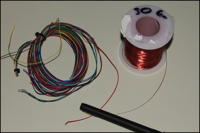
Finally, circling back to my original question: I think I’m safe to use 30 AWG wires for my N-scale decoders, but I’m suspicious that this could be a bit marginal, and that 28 AWG might be a better solution. I’m also thinking about making use of magnet wire for decoder installs, due to the much smaller size of the insulation. A 30 AWG stranded “hook-up” wire is 0.81mm in diameter, while a 30 AWG magnet wire is just 0.285mm in diameter. You can see the two in the photo at the top; that’s a coil of Digitrax “Decoder Wire” on the left, and magnet wire on the right, both in 30 AWG. Both contain essentially the same amount of copper, and both should be able to carry the same current, so if Digitrax wire is okay, so is the magnet wire (as long as it’s copper; they do make aluminum magnet wire and it has different limits).
The Digitrax wire is also pre-tinned, which makes it the equivalent of fairly high-quality hook-up wire. And for long-term use, pre-tinned wire won’t lose its current-carrying capacity due to surface corrosion the way other wire in a damp basement eventually will. That’s something to consider.
Those wires I used last time? There’s no gauge listed, but they appear to be about 26 AWG, which would be good for 1.3 Amps in an enclosed space (if I trust those tables I found), which matches the “for 1A” on the packaging. Good wire for an older HO locomotive, but overkill for my needs.