


Other Lightboards
Up until now I’ve been concentrating on my Kato models as far as DCC conversion goes, and at the same time I’ve only really paid attention to the interior lighting of those cars. Now that I’m working up to large-scale DCC conversion of my non-Kato stock, which is mostly MicroAce and Greenmax at this point, I need to think about lighting the interior of those cars.
And it turns out, they’re pretty much identical. Both MicroAce and Tomix make their own interior lighting kits, and they’re very similar. A third-party company, F&MOKEI also makes lightboards, and claims they work with both manufacturers’ cars. And Greenmax notes compatibility of its cars with Tomix lights (Tomix is far larger a company than MicroAce, so it makes sense they only mention one).
Now I’ll caution that so far I haven’t installed any of these, and I only have one set of MicroAce lighting. I’ll probably buy some of the others to compare. In the mean time, I’ve set up a page with the lighting options from the three manufacturers described on it based on online store pages.
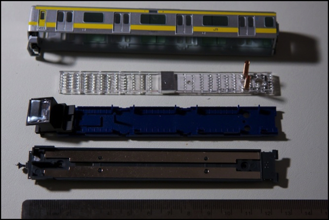
All of these seem to be LED-based, and they come in both narrow and wide versions to fit different trains. One notable difference of these from the Kato lighting is that the color of the light, “white” for fluorescent or “incandescent”, is defined by the version bought. There are no filters to add to change color. All use springs to pick up power from the metal strips under the car floor (via two holes, as seen in the photo at the top of the page). And all appear to have the lights near the middle of the strip, with a lightboard and circuitry at one end, and the other with score marks so segments can be broken off to shorten the prism.
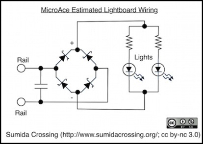
I wasn’t able to read the markings on the resistors through the plastic prism, so I decided to sacrifice one of the of the MicroAce “White, Wide” (G0003/G0004) sets I bought on the altar of science, or at least curiosity, and cut the lens off. This revealed a pair of 680 ohm resistors, a capacitor, and two three-pin “WV4 95” chips, which a bit of googling revealed to be double-diode Schottky assemblies (BAT54S type), so the pair make a full-wave rectifier (if wired that way).
The Schottky is a very efficient diode, dropping at most a few hundred mV, so nearly all track power makes it to the resistor/LED assemblies. The LEDs light at about 2.75V, and quickly become bright.
I think there are three traces running the length of the board. One (on the back) connects to the anode (+) side of both LEDs. The others each connect a resistor to the cathode one LED. This means that each LED has a 680 ohm dropping resistor, and the two LED/resistor assemblies are in parallel. I’m not sure why they didn’t put them in series; it’s a rather inefficient design.
I can’t tell where the capacitor sits, but it looks like it may connect to the track side of the rectifiers. If so, that’s bad, as it could interfere with the DCC waveform on the track.
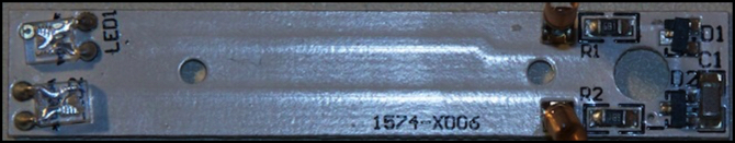
Lightboard front
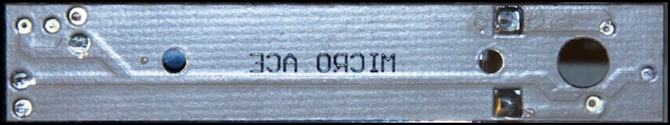
Lightboard back - image flipped vertically, so bottom is same as on front image
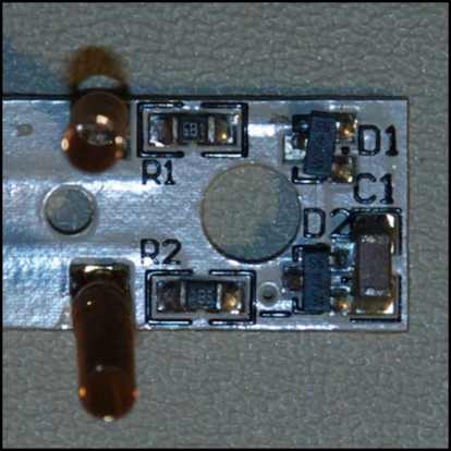
Close-up of the resistors, diodes and capacitor
To understand the function of the resistors, I need to see what current is flowing through them. Using an adjustable DC power supply set to 12V, my meter measured 24.23 mA through the lightboard. That’s twice what I’d expect given a 680 ohm resistor, which means that the two LEDs are not arranged in a linear circuit, but in parallel, each with its own resistor, confirming my assumption from what I could make out of the circuit. I tested at several other voltages, and saw what I expected given that assumption.

Current Test Rig
As noted, I’m not sure which side of the rectifier the capacitor sits on, but assuming it’s on the track side, the circuit looks like this:
An implication of this is that the lightboard should be safe to at least 16V given the 680 ohm resistor, as current should rise to about 19.1 mA at that voltage, so even if it’s a 20 mA LED, it will be okay. At 15.0V I saw current of 32.7 mA, meaning 16.35 per LED, slightly below what I expected (likely caused by normal variation in the resistor from its rated value).
In terms of DCC operation, aside from the mysterious capacitor, the only questionable part is the resistor. At 12V, it’s dissipating just below 125 mW, which is high but reasonable for a SMD resistor of that size. At 16V it would be dissipating nearly 250 mW, and that doesn’t seem safe. To see if there were any problems, I ran the circuit at 15V (the highest my supply will provide) for 40 minutes, and saw the resistor heat to about 40°C. That’s in open air without the prism, and heating under the prism installed in a closed car will be worse, but it’s not very hot for a resistor. I’m not sure I’d want to run for hours at that voltage, but it doesn’t seem obviously harmful.
I’m still a little nervous about the capacitor. I’m going to hook up a train full of these and check the waveform with my oscilloscope to see if its distorting, but that’s a project for another day.
Monthly Status
December was all about electricity, both in my Wire Ampacity work (which is ongoing) and in continued examination of the wire-in decoder issues, plus this recent work on interior lighting. The goal of all of this is to refine my plans for how to handle converting my non-Kato (or older Kato cars that take wire-in decoders) to DCC. I still have a few more things to work out, but I’m getting close to having a plan. Next up is getting the MicroAce E231 finished up as a test-bed with sockets for both motor and cab decoders (I need to re-do the motor one) and then doing some testing of specific decoders and decoder configurations.