


Occupancy Detection Yet Again
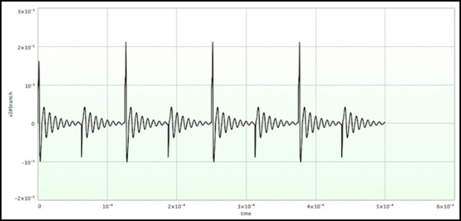
No, that’s not my pulse. I’ve been playing around with occupancy-detection circuits, and that’s a (simulated) current in one of the detectors.
About fifteen months ago work on adding occupancy detection to Sumida Crossing stalled. That was in part because I’d planned to use the BDL168 detectors to also do transponding, and a few months earlier had abandoned that plan since I was unable to get that aspect to work reliably, even on a simple test track. The number of solder joints on the BDL was also a nuisance that caused me to put off further work.
Recently I’ve been rethinking my approach. The BDL168 is an amazingly cost-effective solution. Ignoring the transponding part, you get 16 detectors on a board that includes a LocoNet bus interface for US$120 (street price). That’s $7.50 per detector (if you can use all 16). That’s really hard to beat for a bus-connected detector. I’d originally planned to install one per table on the layout, and my cost would have worked out to around $10 to $15 per detector on average.
On the other hand, I’m thinking that I might want to move to either a OpenLCB/NMRAnet bus (if I want a feature-rich bus for the future) or a really dumb serial bus (like S88 or C/MRI). The latter is attractive since I can potentially interface to it with an Arduino, opening up some room for home-brew devices. Of course I could do that with NMRAnet, but today that requires a US$45 shield to add to the Arduino (or one with it built in), which kind of takes away from the appeal of using $10 Arduinos to do things like drive signal masts.
While thinking about this, I went off and started researching what was available commercially or as home-brew circuitry and software libraries for these busses and for doing occupancy detection with them, as the latter would be a good way to get my feet wet and solve my “don’t want to solder those #$@! BDL168s any more” problem. I’ve put a bunch of info from that research on my Control Bus page and my Train Detection page.
But in the past week I’ve been sidetracked into looking at homebrew inductive-coil detection circuits.
Now induction is definitely the right solution for train detection in DCC layouts. It fully isolates the high-current track circuitry from the sensitive stuff that’s easily reduced to expensive cinders (including my computer: I’ve blown a USB port on a computer before; I’d rather not do it again). And an easy way to do this is to use the NCE BD20, which puts a detector coil on a simple circuit board with screw terminals (I like screw terminals!). Don used this approach with his Io board for OpenLCB (NMRAnet). And I could potentially do something similar with C/MRI boards or perhaps an Arduino.
But the downside here is that the BD20 alone costs US$12 for a single detector, and that’s without whatever you’d use to connect to the bus. That makes it hard to beat the BDL168 cost. With a do-it-yourself detector I can probably get the parts cost down below US$7 per detector, not counting an Arduino. And I can probably drive a dozen or so detectors with a pair of $10 Arduino Pro Minis (one for the detectors, one to manage a serial bus interface). I might get my cost/detector on par with the BDL168 that way, and be able to set up more or fewer detectors per table (some of my tables need just six, others need about 12).
So I’ve been looking at circuits, and there are really only two of them that interest me: one developed c. 2005 by Rob Paisley, and another developed c. 2006 by Reinhard Müller. Both are fairly streamlined circuits that use a single transistor (with some resistors and capacitors) to amplify the coil current. And both can produce the +5V/0V signal levels needed to work with an Arduino. Both are simple enough to assemble that I could do it myself. Soldering is required, which is something of a negative for me, but it’s circuit assembly I can do seated at my electrical workbench (aka the dinning room table), not standing in front of a 24” panel sitting atop my carpentry workbench in the basement.
But I’m inescapably curious, and wanted to understand just how these circuits worked, which kicked off a week of playing with circuit simulations to figure out just what was going on. I’m not done, although I’ve reached a good stopping point, and will probably turn my attention to some other project for a while now. I’ve summarized my testing on the Inductive Detection Circuit page. The long and short of it is that both circuits work, which wasn’t a surprise as both have been used on real layouts. And I now have a handle on the strengths and weaknesses of each, so I can adjust for those if and when I get around to designing something.
Teaching myself enough of SPICE to get the job done was an interesting diversion. And finding a half-decent SPICE GUI front-end for the Mac was handy; I’m using Volta, which sort-of works, but at a cost of a couple of bucks it was a bargain. I’m sure I’ll be using it for other things in the future. And now I think I understand what goes on in these circuits, which is rather cool when you get right down to it. I’ve always been a digital kind of guy, so learning about analog behavior is something fairly new to me.
But I’m convinced that either circuit could be used (both have their own strengths, and I’ll probably build a couple of each kind of detector eventually and compare them to the BD20). And thus the idea of an Arduino-based bus node for detection (and by extension for other things in the future) is a reasonable one.
I still have to decide if I’m going to stick with LocoNet and the BDL168, move to OpenLCB/NMRAnet, or move to (and pick one of) the older simpler bus methods (some of which will only work for detectors, and not signals). But I’ll procrastinate on that for a while longer yet.