


Train Power - DC Motor Basics
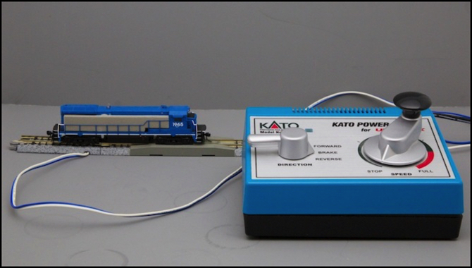
My Atlas test loco and Kato power pack
I’m going to kick off the new year with a series of posts on some basic topics related to model railroading. Hopefully that will give me something to think about while my work on the layout is stalled, and reinvigorate my interest. I’m going to start with several about motors and control systems. Much of this recaps material I’ve covered in the past, but hopefully in a more concise and readable form.
Also, since my present modeling is all N-scale, I’m looking at things from that perspective. Much of this is equally applicable to other scales, although Z-scale motors may be somewhat different (“coreless” motor designs are more common there, and I’m not going to get into that).
While many trains today are used on Digital Command Control (DCC) systems, I’m going to focus on non-DCC systems that you’d find in a typical off-the-shelf model or a basic set, similar to the locomotive and DC power pack shown above. The same motors will work with DCC, with some additional electronics (the “DCC decoder”), so this is a good foundation regardless of the type of layout used. Future posts will cover more complex topics, but for now let’s stick to the basics: simple voltage-controlled motors and DC power.
The information below is intended to start with very basic concepts and move up to more complex ones. Some of the material may seem obvious to anyone who has spent even a moderate amount of time with model trains. But it’s been my experience that not all of the “obvious” things are obvious to everyone (certainly I’ve discovered a few things “everyone knows” years after getting into model railroading). So if something seems “too basic” for you, skip past it, but someone else may care about it.
My DC Train Motors page has more photos of typical N-scale motors, and goes into some of these topics in more depth.
Update: I don’t normally modify Musings after they are posted, but I have made some edits to this one to clarify sections and add some minor details overlooked in the original. These don’t alter the original in a significant way, but may make it clearer to some readers and help provide better background for later posts. I’ve also corrected a couple of factual errors (I seem to make a lot of those).
Direct Current and DC Motors
Model trains, for the most part, run on electricity. That electricity is normally delivered through the rails except in large-scale trains (which often use batteries) or specialized models that use overhead wiring. How the electricity gets to the motor doesn’t really matter for the operation of the motor anyway. It works based on the voltage and current provided to it.
Model train motors are electric motors. That electricity is fundamentally “Direct Current”, shortened to DC, meaning electricity that has a fixed “positive” (plus or “+”) and “negative” (minus or “-“) terminal. Motors use that electricity to create a magnetic field inside the motor. In the case of a typical model train DC motor, this field pushes against a magnetic field created by a permanent metal magnet on the outside of the motor, and causes the central shaft in the motor to turn. That turning shaft can be connected to other things, and that’s how we get power out of the motor.
DC motors have two external electrical contacts (which connect to internal “brushes”) and turn in one direction if positive is connected to the first and negative to the other, and turn in the opposite direction if you swap the two. And you can swap the two at the source, with a switch, which is what the direction switch on a typical model train “power pack” does.
The other thing that makes DC motors useful is that they run at a speed that depends on the voltage. The throttle knob (or lever or buttons) on a DC power pack simply changes the voltage being sent to the rails from zero to some maximum (which we’ll call 12 volts for today’s discussion). This speed is measured in revolutions, or rotations, per minute, or RPM. Finally the relationship between voltage and speed of an unloaded motor is roughly “linear”, so a motor that runs at 14,000 RPM at 12 volts, would run at about 7,000 RPM at 6 volts, and 3,500 RPM at three volts.
Now the real world is rarely that simple. First, 14,000 RPM is a bit fast, so the motor is connected to the wheels through a set of gears that reduce the speed of the wheels. At full speed, the wheels are probably turning much less than 1,000 RPM. Those gears add friction, and friction gets larger (takes more energy to overcome) the faster things move. So in practice a train won’t run twice as fast at 12 volts as it would at 6 volts. But it’s close if the mechanism is in good shape and properly lubricated, and the loco isn’t pulling any cars. Load also matters, which we’ll get to later, and a loaded motor will turn slower than an unloaded one for a given voltage.
At the other extreme is slow speed. Now an ideal motor in an ideal world would start to turn as soon as it had any voltage at all applied to it. In reality there are forces (friction again) that try to keep it from turning. At some point the force exerted by the magnetic field inside the motor overcomes that friction, and the motor starts to turn. That happens when the voltage is well above zero volts, although still likely relatively low.
But it doesn’t start to turn at close to zero speed, instead it turns at a speed based on the voltage. There’s still some friction trying to slow it down, but the friction of moving things (“kinetic” or “dynamic” friction) is usually lower than the friction of stationary things (“static” friction). So what happens is that at some voltage, the motor jumps from zero RPM to some fairly high number of RPM (perhaps several hundred). The actual speed depends on a number of things, and designing motors and power supplies for good “slow speed operation” is fairly complex. But thankfully the people building model trains have been doing this for years, and have a good handle on what’s needed.
Lies, Damned Lies, and Marketing
That said, take this all with a grain of salt. I’ve measured a number of motors in different ways over the last several years, but I’m not an electrical engineer and certainly not an expert on motor design. I’m a hobbyist who knows enough to be dangerous, and likes to take things apart and see how they work. And I’ve never done, and don’t ever expect to do, a comprehensive survey of current model train motors. I don’t even have the right tools to measure some important things (like pulling power, for example). What I say below is what I believe to be true. And I’m unbiased in that nobody pays me to do anything related to model railroading. But I’ve been wrong before, and I could also have a bias I’m unaware of, simply due to the subset of the hobby I’ve been exposed to.
Unfortunately the people who could say something definitive aren’t likely to, and certainly do have a bias. Those are the companies who make the model trains. Companies always want to show their products in the best light. That’s true for both companies with good products, and companies that really have something to hide. But the one thing you can be sure of is that none of them are telling all of the truth, and none of them are providing all of the details you may want to know. They’re going to talk up the good things they have that matter to customers, and skip over anything bad or anything they think doesn’t matter. That’s what Marketing is all about.
For example nobody today, as far as I know, documents the maximum voltage or stall current that their motor can sustain without damage. You may be able to get this for third-party motors used for “repowering”, but not for the original ones. Other important things, like maximum RPM at a set voltage, pulling power, or motor impedance, also go undocumented.
While some companies will tout “five pole” motors, they usually won’t tell you if those are straight or skewed designs. And there was at least one instance of a company that claimed “five pole” only to be discovered selling three-pole motors. It’s quite possible that that was simply the result of the Marketing department not talking properly with the Manufacturing department (Hanlon’s Razor: “never attribute to malice that which is adequately explained by stupidity”).
In sum, if you actually care about the details of how the loco is built or what kind of motor it has: take it apart and look and measure the important numbers. That’s what I’ve done for some of my models, and you’ll never know for sure what’s inside the body of a loco otherwise.
And even then you won’t know if it’s “better” than something else. Are five pole motors better than three? Well, “conventional wisdom” in the U.S. market seems to be that they are, although this may derive from c. 1990 HO-scale five-pole can motors used for repowering being better than what manufacturers were putting in their trains at the time. Kato certainly still seems to like three-pole motors for its domestic market, and while that could simply be a cost-saving measure, there may be a technical reason to prefer them. The fact that U.S. manufacturers tout “five pole” as an advantage doesn’t mean it necessarily is, they’re just responding to their customer’s perception that it is.
Update: further reading has convinced me that five-pole motors do provide a benefit in slow speed running, although that may matter less with DCC than it did with DC (since there are other ways to get good slow-speed running with DCC). There may be negatives that counteract this, see the DC Train Motors page for the latest info on that.
And, of course, a motor is just part of a system that includes the wheels, wheel bearings, reduction gearing, flywheels and drive shafts. An otherwise good motor would still work badly if any of those parts were not the best. You need to judge a model on its own merits, not by what anyone (including me) says about the motor. This is where reading new model reviews in some of the magazines can really be useful, as they’ll often talk about stall current and pulling power as observed in their test unit.
Motor Design
The motors used in typical model trains, at least in the usual scales found in home layouts, are what are called “brushed, permanent magnet motors”. These, as described above, have a pair of electrical contacts (“brushes”) and an outside permanent magnet. The brushes are actually made of some soft material, usually something like the graphite you’d find in a pencil, so on the outside each of these will connect to a metal electrical contact, usually a small button or short strip made of brass.
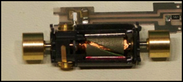
Let’s take a closer look. The photo below is of the motor (and part of the frame) from a Kato N-scale DE10 locomotive, although a very similar design is used for all Kato motors and many motors from other suppliers. The details may vary in important ways though. This is an “open frame” motor since the internal moving parts are not fully enclosed. In larger scales there is often a metal shell around the motor, and these are known as “can” motors.
The black assembly is the motor frame, made of plastic. The pinkish-reddish bit at the bottom of the photo is one side of the permanent magnet (it’s steel, which is silver, but it’s been marked with a red pen or something to show which end is “north”). The two smaller brass circles top and bottom on the right connect to the brushes, and have short brass strips leading away from them, which touch other contacts within the model train to get the electricity from the rails to the motor.
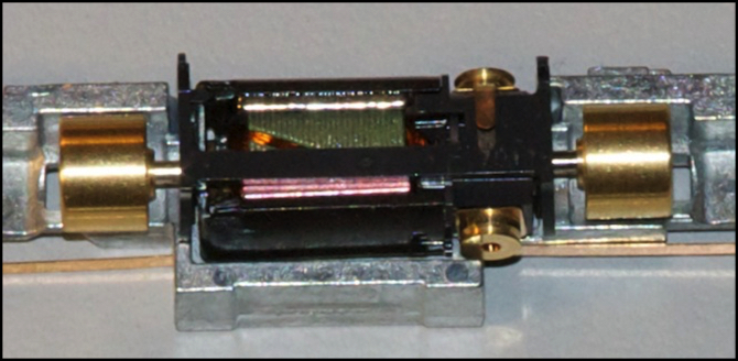
Kato DE10 motor with brass flywheels
Another important detail you can see here, although it’s partially obscured by the frame, is the central “rotor”. The rotor is the assembly within the motor that turns (rotates), hence the name. The frame is sometimes called the “stator” (because it’s stationary), but that’s less common.
The rotor assembly consists of several parts, although the names are sometimes rather loosely used. The “shaft” (or “armature shaft”) is the portion that runs through the motor, and rides on the “bearings” to keep the motor turning smoothly. This is the shiny silver portion seen where it runs from the ends of the motor to the flywheels (flywheels aren’t part of the motor, but rather part of the drivetrain connecting the motor to the wheels). The bearings will likely be located at the two ends of the motor, where the shaft comes out, although they could be deeper inside the ends.
Other parts will be attached to the shaft, including the electrical contacts (“commutator”) and the soft iron or steel portion used as an electro-magnet (the “armature”, seen as the layered gray metal portion above). Very fine insulated copper wire is wrapped around portions of the armature (the “windings”, seen as the orange-red wire in the gap between parts of the armature above).
The armature is actually divided into three or more portions that stick out from the shaft, but which are connected in the middle. I call these “armature lobes” for lack of a better name. They’re sometimes also called “poles”, although that’s not really correct terminology either.
When electricity enters through the brushes and commutator, it flows through the copper wires, and makes the armature into an electro-magnet. It’s the magnetic field from this (the gray steel) pushing against the permanent magnet (the red-painted steel) that causes the central shaft to turn. This electromagnet will always have a “north” pole on one side and a “south” pole on the other. There’s really only one of each, regardless of the number of lobes powered, so the real pole is likely to be near but not exactly at the same place as one of the armature lobes, since there are always an odd number of lobes in this kind of motor.
On this motor, that shaft comes out both ends, and connects to a pair of large brass flywheels. Not shown here (because I removed them) are the shafts from those flywheels to the gears on the wheel assemblies at each end of the train, which turn the actual wheels to make it move.
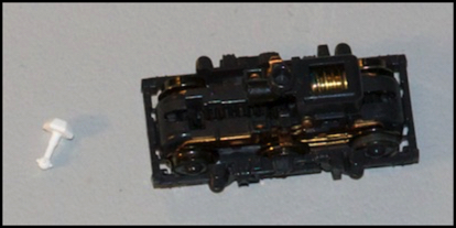
Kato DE10 Truck Assembly with (white) drive shaft
It’s very simple, at least on the surface. There’s actually a lot of complexity inside a motor that isn’t immediately obvious.
Armature “Poles”
The wire “windings” are arranged into three or more sets, each of which is wrapped around one metal lobe and can be connected to the brushes separately from the others (I’m going to skip over the details of how brushes and the commutator work). The following graphic illustrates these parts, along with the external permanent magnet’s “north” (N) and “south” (S) poles.
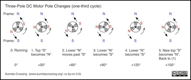
Update: original diagram replaced with a more accurate one. I misunderstood how armature windings were switched, and have now corrected misstatements related to this.
In this image, there are three lobes on the motor, and one has windings carrying electricity in the direction to make it a “north” pole, two others have them carrying electricity in the opposite direction to make it a “south” pole. Since magnetic poles of the same kind push away from each other, these push against the fixed magnet on the frame, and that push causes the motor to turn in a counter-clockwise direction. Eventually the “N” pole will approach the “S” pole of the permanent magnet and be switched, later another “S” pole, which will be off to the left by then, will become the new “N” pole to keep things moving. Similarly, when the “S” pole approaches the “N” permanent magnet pole, the same sequence will occur.
This is why electric motors need to have at least three lobes on their armature, and why those lobes are often called “poles”. If there were just two, magnetic force might line up with the external poles. With three, it’s always going to be unbalanced, and keep the motor turning. In fact, you can use any odd number of lobes, and “three pole”, “five pole” and even “seven pole” motors are used in model trains. There’s a preference today for five-pole designs, at least in North America (Japanese modelers don’t seem to obsess over this detail).
Note: when more than two lobes are powered the same way, the actual magnetic pole will fall between them, since there’s really only one pole of each kind on a magnet.
In N scale, three and five-pole motors are what you will find, as there isn’t room to fit in more without losing too much space to the gaps between them. In HO scale, five pole motors are very common today, but three-pole still exist and you might find a seven-pole motor if you looked long enough. In larger scales (O, for example) you can more easily get 7-pole motors, although I don’t think they’e common.
The benefit of more poles is that a lesser percentage of the total amount of the windings will be the “wrong” polarity as one pole passes a magnet (1/5 on a five pole versus 1/3 on a three pole motor), and this means less power is lost and thus there is less variation in power as the motor rotates. The closer spacing of the poles also probably helps to reduce the variation in power.
Kato, interestingly enough, used five-pole motors on their Japanese N-scale trains until they started making their “DCC Friendly” models (at least since the earliest models I have, they might have used three-pole motors back in the 90’s), then they switched to a three-pole design for DCC use, although they still put five-pole motors in some non-“DCC Friendly” trains. On North American prototype models they appear to use five-pole motors regardless of DCC support, but this may simply be due to the perceived need for them in this market.
I’m not sure what benefit they think DCC gets from the three-pole design, but I suspect it’s related to cogging, which is our next topic.
Cogging and Skewed Windings
As you can see in the photo of the DE10 motor, the edge of the lobe isn’t parallel to the central shaft, but instead is angled. Let’s take a closer look at two motors, the first our DE10 motor, and the second the motor from an older model of a Series 205 EMU, also by Kato:
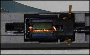
Kato DE10 (left) with skewed windings, and Kato Keiyo 205 Series EMU with straight windings
These are similar in overall design, but you can see some important differences. The motor on the left has the windings angled (“skewed”), while the motor on the right has them straight, meaning parallel to the end of the permanent magnet. Not as obvious, the left motor is a three-pole design, while the right is a five pole design. Finally, the left motor has had flywheels added, which might be coincidence (the flywheel is really part of the drivetrain, not part of the motor), except that Kato has very consistently added flywheels to all of their DCC Friendly models I’ve seen, along with the change to a three-pole motor.
Note: Kato also puts flywheels on five-pole motors in their North American prototype models, but that may be simply because “flywheel-equipped” has marketing value over here. I suspect there’s real value in having them, and the only reason they’re omitted from non-DCC Japanese models is that those are older designs.
Now with a skewed winding, the pole of the electro magnet isn’t all at the same distance from the permanent magnet pole. There’s a downside to this. You need to switch the third pole before it starts passing the outer magnet, or else part of it will be on the wrong side of the permanent magnet, and pulling in the wrong direction. With skewed poles, this needs to be done sooner, so you lose more power. Which might be acceptable, up to a point.
But what it also means is that there’s a smoother variation in the pull as the lobe moves towards one pole and away from the other. It doesn’t reach the same peak level, and the rise and fall is more gradual. This provides a more even force on the drive shaft, at a cost in less overall power. Skewed windings, thus, have benefits similar to those of five-pole designs.
This variation in force as the motor turns can lead to very low power in some orientations, particularly with straight windings, and this variation is known as “cogging”. If a motor is stopped in the wrong orientation, a large variation in strength based on position will make the train harder to start at times, and more likely to stall, and this makes it more difficult to get consistent low-speed operation. So skewed windings help to overcome cogging as a problem for low-speed starting and running of trains.
Thus skewed windings are good if you want to run smoothly at low speeds, and aren’t going to be pulling a huge train. This makes them somewhat more important on switching locos. But today, most designs are skewed, and the motors are efficient enough to have adequate power for large trains.
Kato still makes some of their older EMU models using motors (of a five-pole design) with straight windings, because the designs date from a number of years ago. These are found on models not marked “DCC Friendly” (but since Kato doesn’t tend to put that on product descriptions, but only in the manual, you likely can’t tell until you buy it which kind it is).
The two Kato North American models I have (an SD80 and a GG1, both from about four years ago) used five-pole motors with straight windings as well. Note that the GG1 is compatible with a DCC decoder, so this is one case where Kato didn’t switch to skewed windings for DCC.
My suspicion is that the better low-speed operation possible with DCC makes cogging more of an issue, and that in their domestic market they’re willing to trade the power loss that comes from switching from five poles down to three for the improved low-speed smoothness. The same could also apply with DC, but there it’s harder to get trains to move at really slow speeds, so cogging probably plays less of a role.
Voltage, Current and Power
A DC motor depends on voltage, measured in volts, to control its speed, and electrical current, measured in Amps, to provide “power” to the motor. As we’ll see below, current is related to voltage and speed in a rather complicated manner. Power, in electrical terms, is simply the current flowing multiplied by the voltage between the source’s positive and negative terminals, and the result is called a Watt. So a motor that uses 0.5 amps at 12 volts is using 6 watts of power. For DC, a Watt is often also known as a VA (because it’s Volts times Amps), so it would be using 6 VA. A typical DC power pack will probably provide around 1.25 Amps at 12 to 18 volts, or 15 to 22 VA, more than enough to run two typical N or HO sized locomotives.
The actual current drawn by the loco will depend on load. A modern N-scale loco with no load other than itself and running at a constant speed on level track can draw as little as 30 milliAmps, or mA (0.030 Amps). When pulling a load this will rise, but will likely still remain under 100 mA except under exceptional conditions. It can rise higher briefly when just starting or when accelerating or climbing a grade with a load. And it has a maximum, known as the “stall current”, which can be drawn if something causes the motor to stop turning while maximum voltage is applied. As described below, that’s likely under 500 mA on a typical locomotive, and probably well below that at normal operating voltages.
My past measurements of loco currents are somewhat suspect, as I now know that none of my power supplies really provide clean DC power. They are probably still “close enough” for most purposes, including estimating DCC decoder needs, but I decided the check my Atlas B23 test loco using a bench power supply that produces clean DC and can be adjusted from zero to fifteen volts. Stall current was 330 mA at 12 volts. I didn’t test at higher voltage for fear of damaging it, but it rose linearly with voltage (it was 160 mA at 6 volts), so I’d expect it to be around 410 mA at 15 volts and just under 500 mA at 18 volts, which is probably what I’d use as a worst-case scenario to estimate a “safe” DCC decoder stall current for N scale. The same loco running without any cars drew between 47 mA at dead slow and 93 mA at 15 volts (when it was running well above a scale maximum speed for a freight loco). Obviously with a load, current would rise. I need to do some further tests with it pulling cars, but that’s for another day.
Keep in mind that power packs also provide power for train lighting, turnout relays or motors, and other accessories, so if a power pack is what you use for everything, it needs to have enough capacity for those things in addition to the motors it will be running. But for N scale at least, normal power packs provide considerably more power than is required.
Motors, Torque and Their Effects
Any motor is a device to produce rotational force, known to engineers as “torque”. A physicist would quibble with that since it’s actually force that produces a rotation at a given offset from a center, but for the most part we ignore that kind of detail and just talk about “rotational force”, semi-accurate though it may be. Torque, regardless of how you define it, is what makes the train move. A motor produces a specific amount of torque, but this varies with voltage in a complicated manner (which we’ll get to in the next section). And the force needed to make a train move depends on several things related to friction and gravity, so we can draw some basic conclusions from that without getting into the complexities of the motor.
First, the heavier the train, the more force it takes to move it. So if you add weight to a train, it won’t move as fast for a given motor. Second, there are two places that friction comes into play: the motor/drivetrain assembly and the wheels. Ensuring the drivetrain is free-moving and correctly lubricated helps the train move faster (and smoother), and replacing cheap wheels with better-rolling ones can make the train move faster. The converse is that a train with problems in either of these areas won’t operate as well, because more of the motor’s torque is wasted in overcoming unnecessary friction.
Finally, grades and curves come into play. A train going around a curve has more friction, and the tighter the curve, the more the friction. And, of course, if you recall high school physics, it takes force to raise an object, so any rising grade takes more power than level track. Anything that takes more power will slow a train down if the voltage remains constant. And thus, layout design affects the speed of model trains.
Unless you model Shinkansen or other high-speed passenger service, top speed may not matter. But if you model long freights, these factors also vary with the number of cars, so for a given motor the layout design will define how many cars can be pulled at a given speed (you can pull more cars at a lower speed, since all of the friction-based forces you need to overcome vary with speed, but there’s still a limit).
Optimal Motor Torque and Speed
Torque is rather complex. Ultimately it’s based on the current flowing through a motor, after subtracting what is lost as heat (from electrical resistance in the motor itself and frictional losses in motor bearings and the drivetrain). Current in a motor is based on both voltage, and rather oddly rotational speed. This is because motors work like generators, producing a voltage in the reverse direction as they speed up. This opposes the voltage produced by the power supply, and has the effect of reducing current through the motor, and thus the torque (useful force) of the motor.
This doesn’t mean that a motor runs best at half-throttle (half voltage). What it means is that it produce maximum torque when full throttle (voltage) makes it run at half speed. Trains lighter than that maximum can run as faster speeds, up to the maximum limit defined by the motor’s torque at high speeds and the friction and other forces affecting the train.
That reverse voltage is called “Back Electromotive Force”, or “Back EMF”, and its effect on current is used by some motor control circuits, in particular DCC decoders, as a way to measure the speed that a motor is actually running at for a given voltage. As voltage rises, current should change in a well-understood manner. When it does not then it can be inferred that some load is causing the motor to run slower than optimal, and the controller can vary the voltage (even though the throttle setting hasn’t changed) to provide more voltage, more current, and thus more torque, all to maintain a desired speed.
In a simple DC throttle, without any kind of “feedback” control, a throttle setting of 50% simply means 50% of track voltage is supplied (6 volts if our track voltage is 12). With a more complex motor controller, a throttle setting of 50% would mean “run at half of top speed” (assuming no speed table was used to define it differently).
Note, however, that the limit based on load is still there. If 100% of throttle makes a single locomotive run at a given maximum speed, adding cars will limit the top speed. If that is, say, 80%, then it doesn’t matter if the throttle on a feedback-sensitive control is set to 80%, 90% or 100%, the train won’t run faster. On a simple DC throttle, for the same train the human is the one performing that control function and increasing voltage if needed, and a setting of 100% on the throttle would cause the train to run at 80% speed, while a setting of 80% would cause it to run at some slower speed (i.e., the human who wants 80% speed needs to notice that the train is running slow and turn up the throttle until the desired speed is reached).
As an aside: as you add load (more cars) a locomotive’s speed at full voltage will be reduced, until finally it can’t move. The torque being produced just before it stops moving is the “stall torque”, its maximum at that voltage, and the current drawn to produce it is the “stall current”, which is the maximum current the motor can draw at that voltage. Note that both stall current and stall torque are defined for a specific maximum voltage. Higher voltages produce more of both, up to the motor’s limit (at which point either more current or more force will damage the motor).
You don’t need DCC to have feedback-based control. Based on their marketing materials, MRC’s powerpacks with the “Accutec” feature would appear to be doing the same thing (update: well, maybe not, see my MRC powerpack review). We’ll get more into control systems in a future post.
The motor in either case is doing the same thing: consuming maximum current at half maximum rotational speed, and using more voltage to produce less current as speed increases, or more voltage to produce the same current as load increases and speed decreases. At the heart of things, it’s current that equates to pulling power (and speed for a given load). Voltage, which is what the throttle knob normally controls, only indirectly affects current.
Motor Installation and Contacts
Motors, as we’ve seen above, have two contacts. And they get their power through the two rails of the track. This comes up through the wheel assemblies, and is conducted along brass strips (or sometimes through metal frames) to the motor’s two contacts. There’s a convention for this: when positive voltage is applied to the rail on the “right” as viewed from the engineer’s cab on the loco, the train will move in the “forward” direction.
Notice that if you put the loco on the track “backwards”, the plus rail is now on the engineer’s left (because he’s facing the other way), so the train will run backwards. What this means is that if you have a track running left-to-right, and you apply power so that a loco on the track moves to the right, any other loco you place on the track, whether it faces left or right, will run to the right also. That’s handy if you want to double-head (put two locos on the front of one train) or are using a model of a multiple-unit passenger train that has more than one motor cars (typical of longer Tomix EMU models, as well as some of Kato’s 10+5 commuter train sets).
With a DC train, it’s usually pretty obvious how the motor goes in, so it’s hard to put it in backwards. But if you did, it would run the wrong direction. This could also happen if the manufacturer didn’t follow the standards and wired the motor up backwards. If you add a DCC decoder at some point (assuming the train doesn’t come with a pre-wired decoder socket), you’ll need to know which is the “right rail” contact on the motor to wire it up. But that’s a topic for another day.
Motor Limits and Wear
Like anything with moving parts, a DC motor will eventually wear out. It can also be damaged by overloading it. Motors and their drivetrains also need periodic maintenance to keep them in the best shape. While keeping the track and wheels clean for good electrical pickup, and keeping hair and other things off the axles and gears are all important things. Routine maintenance on the motor mostly comes down to lubrication, and possibly brush replacement.
Just how long lubrication is good for is hard to predict. The factory-applied lubricants will probably work for many years of light service, while if you run trains a lot, or for an extended period at a show, you’ll likely need to pay more attention to this. If you’ve had a motor a long time and it suddenly starts working much worse, lubrication is the first thing to check (re-lubricate the motor bearings and clean and re-lubricate the gear assemblies), although looking for hair or similar things caught in the gears or wrapped around the drive shaft is also a good idea. Good lubrication is a topic in its own right, with different types needed for bearings, brushes and gears (see the Lubricants thread on the JNS Forum for information).
The moving parts most subject to wear are the brushes, which are made of some soft carbon substance. These may be replaceable (Kato’s are, although actually getting the replacements may be hard), or you may need to replace the whole motor when they wear out.
Bearings will also wear out, but if the motor is properly re-lubricated every few years of normal use, those are likely to outlive the owner.
Motors run at their maximum torque (i.e., pulling the heaviest possible loads) will wear out faster than motors used in less demanding applications (at 1/2 maximum torque or less), because heavy load produces maximum current, and this leads to commutator (and brush) wear according to one manufacturer of DC motors. In other words, if your loco can pull 50 cars on its own, you’re best off pulling 25 or less, or double-heading (using two similar locomotives).
A motor can also be damaged by overloading it. Motors use very fine “magnet wire” wrapped around the central shaft. This has a relatively low current limit. Maximum current in a motor is the “stall current”, and as mentioned above this can be drawn when the motor is prevented from turning (e.g., by load above it’s maximum being added, such as trying to climb a grade with a train it could barely pull on level track). If the stall current is maintained for an extended period AND the voltage is too high (creating a higher stall current) the motor can overheat, causing insulation to fail and create short circuits within the motor, or even causing components to melt. If either happens, you need a new motor.
Stall current is based on voltage, so using a supply (power pack or DCC command station) with higher maximum voltage will produce a higher stall current. With simple controls you can avoid this potential problem by not turning the throttle up all the way, but with a feedback-based control (DCC with BackEMF or something like MRC’s Accutec feature for DC power packs) the control will turn the voltage up as the motor starts to stall, even if you don’t. This is why selecting an appropriate track voltage, and a power supply that can provide it, is an important aspect of layout design; one that is all too often overlooked.
Summary
The motor is one of the most critical components of a well-working model railroad train. Of course you need other things: a good power supply, reliable track and wiring, smooth-rolling cars, etc. But the motor is what makes a good loco run smoothly and reliably at low speeds, and pull heavy loads at higher speeds. Without good motors, there would be no “realistic” operation, and we’d still be playing with toy trains.
Modern motors are complex systems, which have evolved over decades to work as we need them to. For the most part, they’re maintenance-free, although over the long term there are things that need to be done to keep them in optimal shape. And understanding the features of different motors may help you evaluate a model locomotive better, although often the only way to discover the important details is to take the locomotive apart and look at the motor.
That’s all for now on motors. In future posts we’ll cover some additional information that only comes into play when what’s driving the motor isn’t really DC, which is actually fairly typical even on “DC” systems today.