


Planning a Test Track
I’ve been thinking about this for about two years now, but it’s finally made it to the head of my “things to do” list: I want to build a short test track using the techniques I plan to use for the new layout: code 55 flex track and turnouts made using the Fast Tracks soldering jigs.
There are several reasons for this: first, I want to refresh my flex-track skills. Second, I want to learn how to use the jigs to make turnouts. Third, I want a fairly complex interlocking where I can try out electronics for detecting trains and controlling signals and interlocking those with turnouts, as well as interfacing all of that to DCC and JMRI running on a computer. And finally, I need to test some trains and see if they have any issues with this type of track.
So the first order of business was to figure out what I want the interlocking to look like. I started by sketching out an interlocking with a couple of tracks and some sidings, which was a nice, generic, interlocking, but not really representative of what I want to model. I’m modeling high-density urban commuter passenger lines in Tōkyō, and those are double-track with few sidings.
So that turned my thoughts to the junction between the Chūō Line and Sōbu Line at Ochanomizu Station, and the set of interlockings just to the west of there, between Ochanomizu and Suidōbashi stations. I’ve done a lot of research on that area, and know the layout of the track and associated signals fairly well. It has a mix of 3, 4 and 5-lamp signal heads, so I can test most and maybe all of the signal types I’d use. Plus it’s a very complex environment, which makes for a good test.
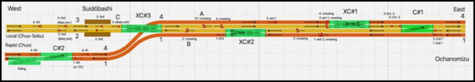
The diagram at the top of the post shows the first ~1.5 km (about a mile) west of Ochanomizu station, including Suidōbashi station. Track numbers are those used within Ochanomizu station (the numbers don’t appear to be used elsewhere). This is not drawn to scale, and is simply intended to show the relationships between signals, crossovers, and stations. The interlocking itself occupies about 1 km of this space.
Here two double-track lines come together to form a pair of express and local double-track lines, with trains moving between them in a complex manner. The Chūō Main Line (these four tracks, although the name is also used just for the two high-speed tracks that bypass stations) is one of the busiest of the very busy urban Tōkyō lines, with daytime headways of “2-5 minutes” according to an online schedule.
It’s been complex for a long time; this line was one of the earliest CTC installations in Japan. Part of the reason for this complexity is historic, as the tracks used to serve freights that came in off the Sōbu Line (which comes in from the north-east and becomes the local pair of tracks) and had to reach a freight yard located to the south of the express tracks. The freight yard is gone now, although a siding with some kind of maintenance equipment and building remains. But the interlocking is still important today. Many trains from the suburbs run as express into the city at peak times, but off-peak they’ll operate as locals and only switch over to the other tracks at this interlocking.
Signal Types and Identification
To model this, I really need to understand how it operates. Since I can’t go to Japan and just sit and watch trains all day, I need to approach this from the perspective of understanding what the track and signals permit for movements. That doesn’t mean that there can’t be others, but routine movements on a line this busy aren’t going to use a manual exception process, they’re going to be controlled by signals.
I’ve posted before on this stretch of track: see here, and here. But I now have updated diagrams on a page for this line.
I should provide a brief overview of the signals. Both Rapid and Local lines are signaled for ATS-P (per Japanese Wikipedia and here), which is a digital form of Automatic Train Stop control with remote transponders that takes speed and braking curves into account to prevent unsafe movements when approaching signals. Central control is exercised using JR’s ATOS system, which allows some degree of local control by station masters (where those exist, which is probably all of these stations) in addition to CTC-type centralized control.
Signals between stations are “block” signals, which are typically numbered in increasing order in one direction, but the numbers may repeat on parallel tracks (i.e., numbers do not reliably identify which track a signal is for). At a station there will be one or more signals permitting entrance to the station, and one or more signals controlling exit from the station. These are often solely under local control. In busy or large stations there will often be mid-platform signals to allow one train to enter as another is leaving, or to allow two shorter trains to occupy the platform without a “call on” signal to override the normal signals. Signals within a station may, but often do not, continue the numbering between stations, which I think means that they’re part of the CTC block system also.
This means that a signal can’t be clearly tied to a given track by its labeling, although you can sometimes deduce that from the sequence of numbers.
Many of the non-block signals are four-lamp or five-lamp signals, providing speed indications for Restricted (25 kph) or speeds between Caution (~40 kph) and full speed, or both. Maximum line speed on the Rapid line is (per Japanese Wikipedia, the U.S. version appears out of date) 115 kph (71 mph), while the Local line is limited to 95 kph (59 mph).
Track Layout and Signal Use
For the Rapid (express) tracks, signals are numbered from #1 at Shinjuku, incrementing to #14 (I think) just west of Ochanomizu. Interestingly the numbers are carried through Yotsuya (the sole Rapid station between the two ends). The local line is numbered similarly, except that the count appears to go up to #27 just west of Suidōbashi station. Most of the signals in between Ochanomizu and Suidōbashi are not numbered, but are entrance or exit signals (these will have Kanji labels designating which kind, and the Kanji for one, two or in one case three, to denote signals of the same type in sequence. For example, the eastbound Local line has three sequential entrance signals approaching Ochanomizu, allowing three trains to be queued up waiting to enter without fouling the previous station. East of Ochanomizu the numbering restarts, in the same, decreasing, direction (counting down as you move east).
After last year’s review, I still had some unanswered questions. Chief among them was why it appeared that some of the tracks supported bi-directional operation. That’s not typically used on busy double-track lines in Japan. The switches didn’t really seem to support this either, as without crossovers in more places it would be inefficient at peak times, which is when you might want that flexibility.
Photos hadn’t shown enough detail of the signals, so I ended up watching a bunch of YouTube cab videos. One of the nice thing about Japanese commuter EMUs is that you can see out the front from the passenger compartment, so there are a fair number of “cab ride” videos out there (just search by station and line name, usually for major terminal stations like Shinjuku; you can find additional videos by using the Kanji forms of the names).
Not all of these have enough resolution to read the signs on signal masts, or even count the number of lamps per head, and often the photographer is more interested in photographing passing trains than the side of the track with the signals, but eventually I’d mapped out most of the signals between Shinjuku and both Tōkyō and Akihabara. I still haven’t spotted all of them, although I suspect the others were just in odd places fairly hard to see from well inside the train where these videos are taken.
I’m focusing on a subset of the line for now, from Yotsuya where the four tracks come out of a tunnel, along the riverbank to Ochanomizu, where the two lines split for Akihabara and Tōkyō. And for the test track, I really only care about the complex interlocking immediately to the west of Ochanomizu.
One thing I discovered was that this line often places signals on the far side of another track from the controlled line. That’s very strange, particularly where there are overhead catenary bridges where they could have placed them (and did in one instance), but it’s fairly clear from the signal mast numbers (where they’re numbered) that that’s what was going on. When this happens, they’re on very tall masts you can see over intervening trains, except when you’re close to the signal.
With that understanding, I set out to reduce my notes to the summary diagram at the top of this page. It’s not to scale, and it may contain errors of interpretation. But on it I’ve mapped each signal to the track I think it controls, and for the most part this isn’t ambiguous. And what’s clear from this is that the signals are not set up for bi-directional use after all. Probably. I still have one place I don’t understand.
A Puzzle
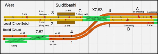
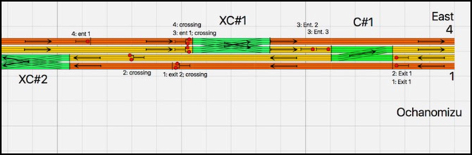
That diagram is a bit of an eye-chart, so here’s an enlarged view:
and
As you can see, at the right end (just west of Ochanomizu) the Chūō Line from Tōkyō (orange) is on the two outer tracks, and the Sōbu Line from Akihabara (yellow, and which is generally known as the Chūō-Sōbu Line here) is on the two inner tracks. On the left side (west) these become the Local (yellow) and Rapid (orange) lines. The interlocking allows trains from either line on the left to move to either line on the right, for the permitted direction of travel.
In truth, only the first two double-crossovers (“XC#1” and “XC#2” on the diagram) are used for this. The single crossover (“C#1”) appears to exist to allow a westbound Sōbu Line train that terminates at Ochanomizu to move west past the station and reverse back in to become an eastbound.
What puzzles me though is the third crossover (“XC#3”). It’s located just east of Suidōbashi station, so it could be used for an eastbound local terminating there to reverse and become a westbound, but you only need a single crossover for that. And that seems like an odd place to reverse a local, unless it is to avoid congestion at Ochanomizu, which I suppose makes some sense although I haven’t found any documentation to suggest that any trains do this.
There appear to be three signals controlling access to this crossover, which I’ve labeled “A”, “B” and “C” on the diagram. B and C make sense for normal operation, but A is an oddity. However, A is one of the signals where I haven’t found a clear view of any label. And although it’s to the right of track 3 and above the tunnel used by track 4, it’s possible that it’s either a wrong-way signal for track 4 or a home signal for track 2 and the crossover (even though it’s not far past the prior signal for that track).
My best guess (ignoring the mystery signal) is that the purpose of this crossover, despite its proximity to Suidōbashi station, is actually to allow trains from Akihabara to reverse and head towards Tōkyō, and vice versa. Now you wouldn’t do that normally. But it could be used to position new trains in Tōkyō at the start of a busy period, or remove them at the end. This is the most likely explanation I can come up with that would justify the extra complexity.
For modeling purposes, I’ll probably use that interpretation, and I may omit the crossover for my test track, as it’s really not essential to the crossover function of the interlocking.
Iidacho Station
The last bit here is the remnant of the yard at what used to be Iidacho Station. Originally a freight yard, later downgraded to just a terminal for newsprint boxcar unit trains, it closed for good in 1999, which I think is when freight stopped running along this line. JR Freight kept their offices here until 2011. Today it appears to be a small maintenance or rescue terminal, with some specialized cars parked on a couple of sidings. The single crossover here allows traffic to and from the station to get to either of the two Rapid tracks.
And this could account for the double crossover at XC#3 and signal A. A vehicle departing the siding that needed to get to the Local line would have to run east to XC#1 and reverse, using XC#3 to get onto the westbound track. This would provide a reason for a wrong-way signal at A, and for the 3 to 2 crossing. A train running the other way would use the other side of the crossover, and XC#2 to get to track 1. I’m not convinced that’s the reason. The single crossing at C#1 would work just as well, except that the crossing train would briefly appear inside Ochanomizu station.
Is not fouling a station for five minutes sufficient justification for a double-crossover and signal? In a lot of places it would be, but Japanese railroads tend to avoid infrequently-used switches as a potential source of failures. To have something this complex on a line this busy, implies some greater need. Which is why I think my previous explanation is the better one. Although with the crossover in place, it’s likely used for both purposes.
Summary
So I understand the interlocking, or at least I have a logically-consistent explanation of it, which I can use to model it. And that provides for some fairly complex movements between the four double-track lines (two east, two west) approaching it, which is what I’d hoped for.
My next step is to try to fit this on a pair of 4’ long tables I can set up for testing on my dining-room table (former home of the Kitchen Table Layout), and take down when not needed. To do that, I need to draw it in XTrackCAD. The diagram here was done with RailModeler. That’s useful for a quick sketch, but it doesn’t have the right track elements for Fast Tracks (and I don’t feel like making them). And ultimately, XTrackCAD is what I’m going to use to design the new layout, so getting in more practice with it will be helpful.
Free time is in short supply, so this project may move slowly. But my intent is to make periodic posts as I go, rather than trying to wait until it is done for a summary post, since that might never come, and regular posting has proved in the past to motivate me to actually do something on the layout when I had a free minute or two. So hopefully, I’ll have more to say in a couple of weeks.