


Bus Wiring and November 2011 Status
DCC is often said to simplify a model railroad because it requires “only two wires”. While that’s true to an extent, most real model railroads will require quite a bit more. Or maybe I just like to over-complicate things.
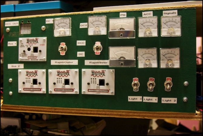
The picture above is of my main power management panel. All of the various layout wiring runs through this, mostly so that it can be monitored, although there are a few switches. There are a few additions to this since the last photos were published a year ago, the two slightly larger meters were added to monitor the new PM42 power bus and the third lighting circuit (which also has the third on/off toggle switch labeled “Light 3” below it). The two meters in the top, right, are for the other DC power busses, for the “Accessories” (DS64, and other things) and “Signaling” (BDL168 and SE8C), the two two meters to the left monitor DC power from the PS2012 power supply to the DCC Command Station (DC1, on left) and the future booster (DC 2, on right). Finally at the far left is the RRampMeter used to monitor output from the command station to the track.
Note: the new meters differ from the old ones because my local store changed suppliers. The new meters are actually better, since they have a 0-5A scale rather than the 0-10A scale of the older ones. Unfortunately they’re also a bit larger, so I can’t merely replace my older meters. Maybe someday I’ll re-do the power panel with new meters, but that’s not happening any time soon.
Below the two left meters are the toggles that switch the outer loop tracks from DC power packs (the two Kato packs you can just see at the top of the image) to DCC operation. And below the RRampMeter is the UR92 panel that contains the receiver for the wireless throttles. Finally, along the bottom are the three LNRP LocoNet repeater panels that subdivide the LocoNet bus.
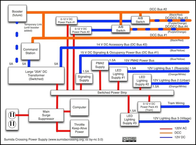
Power Wiring (larger image in Diagrams album)
But perhaps I’m getting ahead of myself. Let’s take a step back and consider all the wiring on the layout (see diagram above). First, there are the “two wires” of the DCC track power bus. These are heavy 14 gauge wires that parallel the tracks and run under all of the tables making up the layout in a roughly thirty-foot long “C” shape; basically an oval with a break in the far side. The command station output connects to the middle of this, through the RRampMeter on the panel, so at most the power has to travel 15 feet from the command station. There are actually two sets of these, to allow for future separation of the commuter line from the other two lines with the addition of a booster, although today both are powered by the lone command station.
Each of the tracks of the outer (“Rapid/Shinkansen”) loop has its own 14 gauge bus wires, which have a DPDT toggle (“A/B switch”) on the power panel allowing them to be connected to either the second DCC track bus, or an individual Kato power pack (the latter is used for testing and breaking in new trains, and for running trains that haven’t yet been converted to DCC).
In addition to those wires, there is a power bus for accessory systems (like the DS64 turnout controls), a separate power bus for the PM42 circuit breakers, and a third power bus for the BDL168 and planned SE8C signal controller. All three of these allow one power supply, which is either an output on the PS2012 or a “wall wart” transformer, to power multiple devices. And all three go through ammeters on the power panel illustrated at the top of the page, so I can monitor how much load is on them.
On each table, there is a terminal strip connected to the track and other bus wires via drop wires, and the track bus on this this feeds into the PM42/BDL168 power board described last time. In the photo below, of the wiring on the “unsceniced” portion of the layout, the terminal strip on the right is one end of one set of bus wires on that table (the wires loop from it out the top of the image). The terminal strip just left of the DS64 is the local drop, and you can see the blue “suitcase connectors” that it uses to tap into the bus wires. The blue/gray wires leading from it are one of the two switched DC/DCC buses for the outer loop of track, and the yellow/orange wires are the Accessory Power leads going to the DS64.
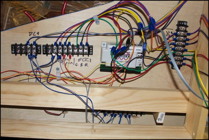
DS64 and Bus Wires (see DCC Systems photo album for larger image)
Although only one set of three buses (plus the green ground) are shown above, each table actually has two of these sets of wires, the second set carries the other four busses. Not counting the lighting bus for a table (which is separate) there are a total of seven pairs of wire, plus a ground, running under each table.
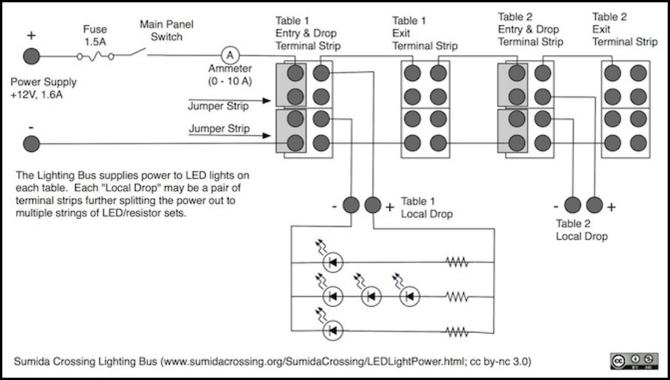
The lighting bus is done somewhat differently. Each “scene” has a single lighting bus, with a single terminal strip at each end of each table, which allows for a limited number of local drops direct from the terminal strip. One of these “local drop” wires can be connected to additional terminal strips if more wires up to scene lighting are required. Wires up to the scene will typically connect to foil tape power busses that are used to provide power to multiple buildings, each with one or more sets of LEDs within it.
The last bit of wiring is the LocoNet control bus. This is actually three parallel systems, although one of them is only present on the electrical shelf, connecting the local UP5/UP92 panels used for throttles. A “protected LocoNet” links the three LNRP repeaters that subdivide this bus, and also connects to the command station (DCS100) and the computer (RR-CirKits LocoBuffer USB). If I ever add that planned booster, the protected LocoNet will connect to it as well.
The two LocoNet lines that run under the tables are those used for accessory devices (mainly the DS64 turnout controllers) and the signalling bus (used to connect the BDL168 block occupancy detectors, PM42 circuit breakers and planned SE8C signal controller systems).

The LocoNets differ from the other busses in not being wired to the tables themselves, but merely looping in a daisy-chain between systems that are attached to the tables, or to removable boards such as the PM42/BDL168 panels.
It’s all a lot more than “two wires”, and probably needlessly complex for a layout this size. However, the layout was designed with the intent that it could be expanded in the future with new scenes, or converted into an “along the wall” layout if I ever get a large enough basement. And the wiring will easily support such use.
For more about the bus wires and related systems, see my Wiring Design, Wiring Standards, Block Wiring, DC Power Supplies, Lighting Power, and LocoNet Overview pages.
Monthly Status for November 2011
Well, November went mainly to work on the power systems, so this musing makes a nice cap to that (not that I’m done). I’ve been installing the new power panel on the River Crossing scene and getting the bus wiring expanded, as well as building the fuse box that provides power to those busses, and adding the new switches and meters to the power panel discussed at the top of this page.
Still to come are more PM42/BDL168 boards, more work on the bus wires and bringing the “village” lighting bus up into the village itself, so I can start wiring up streetlights and building lighting there. I expect I’ll be at this for a number of months yet to come, although it’s beginning to feel like I can see the end now.
